The invention can be used in the chemical industry and in the manufacture of stationary and transport fuel sources. Iron oxide is reduced by thermolysis when heated with an inert gas to produce oxygen at temperatures above 1200°C and pressure above 0.1 MPa. The iron is then oxidized by a stream of water vapor heated by an inert gas in a container alternately filled with heated inert gas and water vapor. By adsorption, or membrane, or electrochemical separation, hydrogen is separated as the final product from a stream of water vapor, as well as oxygen from a stream of inert gas. The cycle of oxidation and reduction of iron oxide is carried out in parallel switchable sections connected by inert gas and water vapor. 8 salary f-ly, 1 ill.

Hydrogen production. Hydrogen production (production) installations.
Introduction
The indoor hydrogen production unit is a comprehensive hydrogen production unit with a hydrogen production capacity of 30 nm³/h at a purity of 99.998% and a pressure of 10 barg. The
unit is fully automated, which significantly reduces the operator presence (maintenance) time. The installation is designed for completely continuous operation, the hydrogen flow rate at the outlet is automatically adjusted to the user's requirements. Thanks to the careful selection of the main components used, maintenance requirements are kept to a minimum.
Reliability
Special efforts have been made to ensure the highest level of security for our customers:
- The protocol ensures safe shutdown in the event of a failure in the control system (PLC)
- Continuous Atmospheric Hydrogen Detection (HTA) System
- Reliable logic circuit for all parameters (more than 30 parameters are monitored)
- Uninterruptible Power Supply (UPS) provides shutdown in case of power failure
- Continuous gas purity monitoring (HTO)
- An inherently reliable design (passive safety), which allows the installation to perform an emergency mechanical pressure release in the event of failure of the controls.
- Minimal presence of gas in the system (only a few Nm³/h at full production)
- Multiple redundancy for critical reliability parameters. In addition to the standard transmitters, each safety parameter is also monitored by a safety relay, which triggers an alarm or stops the unit in the event of a disturbance in normal operation (e.g. electrolyte level, cell pack temperature, system pressure, ...).
Automation
The hydrogen production plant is carefully designed to operate continuously with minimal human intervention required while maintaining reliability levels in accordance with the most stringent industry standards.
The plant starts and maintains hydrogen production fully automatically, while key safety and production parameters are continuously checked at the same time. The following features are included as standard in our installation:
- Hydrogen pressure control:
The HMI (Human Machine Interface) on the control panel allows the operator to select the required gas pressure (between 6 and 10 barg). The unit automatically adjusts the performance coefficient to maintain the set pressure (optionally a pressure reduction valve can be added to meet customer requirements). - Hydrogen Flow Control:
Based on pressure, hydrogen production and consequently hydrogen output is constantly adjusted within operating limits to follow actual demand. Hydrogen will be (partially) released into the atmosphere for a maximum of 20 minutes if the demand is below the minimum plant capacity. - Automation of cooling:
The flow of cooling water entering the heat exchangers is constantly regulated by PLC (thermostat control). This function ensures a constant operating temperature for the electrolysis process. - Remote I/O
: Using a modern connection, we have significantly reduced the number of connecting cables and therefore the time required for installation. The implementation of puncture in combination with a safe PLC and safe I/O allows the system to fully comply with the most stringent current regulations and safety standards. The PLC automatically diagnoses any communication errors, not only making the system safer, but also reducing troubleshooting time and effort. - Semi-automatic nitrogen purging:
Nitrogen purging is necessary before starting the unit when the internal pressure is below 15 kPa. The system's PLC sequentially activates the various valves in the system, thus ensuring that all air is evacuated before hydrogen production. The only manual action required is to change the position of the two valves. This action can be optionally automated so that this action is performed by a remote operator.
Installation control and monitoring
Features of the advanced control panel and monitoring capabilities:
- Remote Monitoring:
Allows the operator to access the HMI screen located on the control panel and operate the electrolyser from a remote connection. It displays process parameters, dynamics, events, alarms, and allows the operator to enable/disable individual element packages. - Key Switch:
Allows the operator to start/stop the unit. For safety reasons, to start the installation, it is necessary that both the internal and external switches with the key are in the START position. - Reset Button:
Resets the safety circuit after tripping. Once the reset button is pressed, the unit enters production fully automatically after completing the safety initialization procedure. - Emergency Shutdown:
When this button is pressed, the system immediately turns off power to cell packages and auxiliary support systems and relieves system pressure. Due to this, the system will be switched to safe mode to avoid an emergency. - Touch Screen Human Machine Interface (HMI)
: The HMI screen is located on the control panel and allows the operator to monitor and operate the electrolyser either from the screen or from a remote connection. The monitoring system includes data recording on a compact flash card. It also allows our technicians connect to the electrolyser to diagnose and correct fault cases and alarms if necessary. The PLC uses Siemens S-7 software.
Scope of delivery
Basic equipment
Technology discount
The key component of the electrolysis skid is a package of bipolar cells for electrolysis of water under pressure. The cell stack consists of annular electrolysis cells, each containing two electrodes and one alkaline inorganic ion exchange membrane.
Generation of H2 and O2 occurs when current is applied to a stack of cells. The gases are then directed to a gas separator, which is a double stainless steel pressure vessel, after which they are washed in a specially designed pressure vessel located above the gas separator.
The equipment of the technological part is made of high quality materials and complies with ATEX directives.
This equipment is intended for indoor installation only. Please note that the hydrogen production part is classified for Zone II use only. However, if the process part is protected by an optional ATEX enclosure, these Zone II requirements can be ignored. In this case, the installation location is required to be “general purpose”.
The technological part is supplied as a fully assembled skid, which includes equipment, for example:
- Cell Packs
- Gas separators, hydrogen gas scrubbing unit and coalescing filters
- Heat exchangers for electrolyte and gas cooling systems
- Leak detector tray with level switch
- Hydrogen Detector (HTA), Hydrogen in Oxygen (HTO) Analyzer Panel
- Bale devices and distribution boxes: sensors, transmitters, relays, etc.
- Valves and vent manifolds (H2 and O2)
Control Panel
The control panel cabinet includes a PLC and all related equipment to ensure automatic and reliable operation of the plant. The control panel will be connected via cables to both the process part and the power rack. Characteristics:
- Approved electrical enclosure with 2 lockable doors
- Cooling fans + air filtration system
- PLC (Siemens S-7 software)
- External: terminal with display for visualization and HMI
- Emergency stop on the housing door
- Uninterruptible power supply for safe shutdown
- 24 V DC current power supply
- Circuit breakers and transformers
- Printed Circuit Boards and Sound Alarms
Power rack
The power rack converts the incoming 3-phase AC power into the stabilized DC current required for the electrolysis process. It includes:
- Cover with lockable door
- Cooling fans + air filtration system
- Door switch safety interlock
- Transformer
- Rectifier
- Circuit breakers, starters, thyristors and bridge rectifiers
- Measuring cell packages with an ammeter and a voltmeter on the door
- Phase checking device
Hydrogen purification system
The hydrogen purification system is designed to further purify hydrogen to a minimum level of 99.998%. This purity is achieved in 2 stages:
Step 1: To reduce the O2 content in the H2 gas stream using a catalytic reaction. The yield of O2 to H2 is less than 10 ppm or optionally less than 2 ppm.
Stage 2: Drying: to remove moisture in 2 drying columns. One column is in operation, while the second is in reserve/regeneration mode. The hydrogen output will have an atmospheric dew point of less than -60 °C or optionally less than -75 °C.
The hydrogen purification system is designed on a skid and is located in the process room. The hydrogen purification system is controlled by a central PLC in the control panel and has the following features:
- Deoxo vessel with catalyst for removing H2 into O2 (heated and insulated)
- Heat exchanger
- Coalescing filter
- Drainage vessel system for removing water
- Instrumentation equipment
- Two molecular sieve drying columns (heated and insulated) (with temporary regeneration)
- Connections upstream of the gas cooling circuit
- Connection to the ventilation manifolds of the process part (H2 and O2)
Chiller (gas cooling)
The chiller supplies low-temperature cooling water in a closed loop towards the process hydrogen and oxygen gas heat exchangers of the plant at a temperature of 15 °C, regardless of the ambient temperature. The chilled water cools the hydrogen and oxygen gases, turning the water vapor produced during the electrolysis process into condensate. It is then filtered and removed from the gas stream. The chiller is installed inside an enclosure for indoor use and includes a pump and expansion tank.
Chiller specification
| Environmental conditions | Ambient temperature range environment | +5 to +45°C |
| Temperature, cool water | +15°C | |
| Installation | Dimensions (HxWxD), m | 1.35 x 0.88 x 0.8 |
| Empty weight | 185 kg. |
Electrolyte cooling system
This cooling system is used to cool the electrolyte and chiller and includes a pump skid and a dry cooler that releases heat to the surrounding air. Cooling water circulates in a closed circuit through a high-performance electrolyte-water heat exchanger installed in the technological part of the hydrogen production plant.
Thanks to the closed cycle cooling system, the plant's full hydrogen output capacity is guaranteed between -20°C and +40°C (-40°C or +50°C optional) ambient temperatures. The dry cooler and skid pump are controlled by the central PLC in the control panel.
Dry cooler specification
| Ambient conditions environment | Ambient temperature range environment | 20°C to +40°C |
| Temperature, coolant output water | ambient temperature environment + 3°C | |
| Max. ambient temperature environment for 100% yield | +40°C | |
| Noise level at 10m from the fan | less than 69 dBa | |
| Installation | Dimensions (LxWxH), m | 2.7 x 1.5 x 1.7 |
| Empty weight | 322 kg. |
Feed water preparation system
The feedwater treatment system (wall mounting) converts tap water into pure demineralized water needed for the electrolysis process. Water quality is constantly monitored before it can enter the process. Dimensions HxWxD – 1.5x1.0x0.5 m
The system includes such filtration treatment stages as:
- Reverse osmosis membrane
- Mixed type ion exchange system with resin (2 tanks filled with resin)
- Water softening system with digital dosing pump (anti-scale)
- Conductivity meter
- Activated carbon and particle pre-filters
- Pressure indicators and relays
Tap water is provided by the customer and must meet or exceed the following specification. Please note that 1.5 to 2 liters of tap water will yield 1 liter of pure water and that the electrolytic reaction will require approx. 1 liter of pure process water to produce 1 nm³ of hydrogen. Please note that some of the tap water will need to be drained to remove minerals and some will be returned to the reverse osmosis membranes.
Feed water specification
| Tap water consumption | 1.5 – 2 l/nm³ hydrogen (H2) | Ba2+ | 0.05 mg/l max. |
| Temperature | 10°C – 30°C | Ca2+ | 20-50 mg/l max. |
| Pressure | 2-4 barg | Mg2+ | 10-30 mg/l max. |
| There is no microbiological contamination | — | Cl- | 150 mg/l max. |
| Langelier index | 2.5 max. | SO42- | 150 mg/l max. |
| pH | 7,0-8,5 | HCO3- | 100 mg/l max. |
| Free chlorine | 0.02 mg/l max. | Fe (general) | 0.5 mg/l max. |
| Suspended solids | 0.05 mg/l max. | Al (general) | 0.05 mg/l max. |
| CO32- | 0.5 mg/l max. | Electrical conductivity | 1000µS/cm max. |
| Turbidity | NTU < 0.5 | SiO2 | 0.5 mg/l max. |
| Na+ | 200 m g/l max. | Manganese | 0.05 mg/l max. |
| K+ | 50 mg/l max. |
Feed water treatment system inlet water specification
Data sheet
| Output | H2 production | Consumption | 12 to 30 Nm³/h |
| Purity (before hydrogen purification system) | 99.9% (*H2O saturated) O2 < 1.000 ppm | ||
| Purity (after hydrogen purification system) | 99.998%; 02 < 2 ppm; N2; 12 ppm Atmospheric dew point: -60°C (-75°C with improved purity) CO+CO2+THC < 70 ppb | ||
| Operating pressure at full flow | 10 barg (after hydrogen purification system) | ||
| Number of element packs | 2 | ||
| O2 production** | Nominal flow | resettable | |
| Power | Power requirements | Calculation of power consumption at full flow without auxiliary support systems | 5.0 kW/Nm³ |
| Voltage | 3 x 400 VAC ± 10% 3 x 480 VAC ± 10% (standard in US option) 3 x 575 VAC ± 10% (standard in CA option) | ||
| Frequency | 50 Hz ± 3% 60 Hz ± 3% (standard in US and CA options) | ||
| Installed power | 1 x 240 kVA | ||
| Support systems | Nitrogen for purge | Pressure | 4 to 10 barg |
| Quantity per blowdown | approx. 2 nm³ | ||
| Cooling water | Electrolyte cooling circuit *** | Provided by closed loop cooling system If not included: - max. water temperature: 40°C – max. flow rate: 4 m³/h | |
| Gas cooling circuit | Provided by chiller If not included: - water at 15°C - max. flow rate 0.2 m³/h | ||
| Feed water | Deminer consumption. water in process process | < 1 l/Nm³ H2 | |
| Consumption of tap water in a reverse osmosis installation *** | 1.5 – 2 l/Nm³ H2 (depending on the quality of tap water) | ||
| Pressure | 2 to 4 barg | ||
| Air instrumentation | Min. pressure | 6 bar (air compressor as option) | |
| Consumption (without control valves) | ± 80l/min (not constant consumption) | ||
| First filling | Electrolyte | Type | H2O + 30% wt. KOH |
| Quantity | approx. 500 l. | ||
| Installation | Environmental conditions environment | Ambient temperature range environment | +5°C to +40°C |
| Max. temperature for 100% output parameters | +40°C | ||
| Installation area ***** | indoors, general purpose area | ||
| Relative humidity | < 95% | ||
| High mark | < 500 m |
The above data is provided for information only and is subject to change without notice. Technical data cannot be used for warranty purposes.
(**) Oxygen use requires the optional "oxygen use" feature (***) Only applicable if the "closed circuit cooling" option is not selected. (****) Based on the fact that the reverse osmosis feedwater treatment system is included in the scope of supply. (*****) The process part must be equipped with an optional ATEX enclosure (ATEX zone II without enclosure).
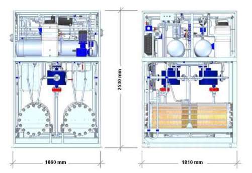
Dimensions:
| Technological part Empty weight ~2450 kg Operating weight ~ 2900 kg | ||
| ||
| Power rack Total weight ~1500 kg Total weight ~450 kg | Hydrogen purification system Weight ~600 kg | Control panel Dimensions: ~ 900x900x2300 mm Dimensions: ~ 1000x1000x2000 mm |
Additional (technological) options on request:
Purity Improvement -75 °C 2ppm
O2
This option reduces the atmospheric dew point of produced H2 from -60 °C to -75 °C and the O2 content of produced H2 from 10ppm to 2 ppm.
Reduced N2 content - atomizing sprinkler
An atomizer is a device installed at the demineralized water inlet of a hydrogen production plant to reduce the N2 content to less than 2 ppm of H2 produced. This will allow us to achieve 99.999% hydrogen purity.
Real-time cleanliness measurement
The H2 produced is continuously monitored in real time, both in terms of water content (“dew point”) and oxygen content. This option can only be selected in combination with a hydrogen purification system.
Drain valve (only in combination with real-time cleanliness measurement system)
This device automatically releases H2 into the atmosphere if its quality does not meet specifications. This option can only be selected in combination with the H2 real-time purity measurement system.
Oxygen use
As a standard, O2 is released into the atmosphere. The manufacturer can provide an optional system for purifying O2 and preparing it for further use/purification by the customer.
Air conditioning system on the control panel
This is a modular air conditioning unit installed on electrical panels. This device is recommended for systems frequently operated at ambient temperatures. environments more than +40 °C, but below 45 °C
Mass flow meter
A mass flow meter is a direct measurement of the volume of H2 flowing into the customer's line.
Oxygen content in the atmosphere detector
An atmospheric oxygen transmitter can be implemented in a process room to continuously monitor the O2 level in the process room atmosphere. The alarm system sounds if oxygen levels fall below or rise above safe limits.
Back pressure regulator
Guarantees the performance of the installation by maintaining the generator and deoxo dryer at a stable pressure. Fluctuations in the customer's line will not affect the pressure in the process part (will be added to the installation if directly connected to the compressor).
Instrument air compressor:
Compact yet reliable bale air compressor for general purpose installation to eliminate the need for external bale air supply.
Direct connection to renewable energy sources:
We can offer tailored approaches to directly connect an electrolyser to renewable energy resources (eg power-controlled electrolyser), providing an efficient, high-performance system optimized for a specific application.
Automatic restart
This function allows the installation to continuously determine the current pressure in the customer's line. If the installation is in standby mode, this function can be used to automatically restart the installation as soon as the customer's line pressure falls below a preset threshold.
Automatic N2 purge:
Allows the entire sequence of N2 purge and hydrogen purification system to be carried out automatically. Nitrogen purging is required before starting the unit if the internal pressure is below 15 kPa. The system's PLC activates the various valves in the system in stages, ensuring that all air is removed before hydrogen production begins.
Contents:
- Electrolyzer – 1 pc.
- Package of elements 15 nm3/h – 2 pcs.
- Control panel with monitoring system – 1 pc.
- Power rack - 1 pc.
- Connecting cable – 1 pc.
- Hydrogen purification system - 1 pc.
- Quality control of incoming demineralized water
- Chiller for gas cooling – 1 pc.
- Closed loop cooling system – 1 pc.
- Atmospheric Hydrogen Detection System (HTA) – 1 pc.
- Feed water preparation system – 1 pc.
- Water tank with a volume of 20 m3 – 1 pc.
- Spare parts
- Consumables for 1 year
- Standard tool kit
- Commissioning works
Electrolysis of water in industrial hydrogen generators
Electrolysis
This is a redox reaction that occurs only under the influence of electricity. In industrial hydrogen generators, water is electrolyzed to produce hydrogen and oxygen. For the reaction to occur, two electrodes must be placed in the electrolyte, connected to a DC power source:
- Anode
is the electrode to which the positive conductor is connected; - Cathode
is the electrode to which the negative conductor is connected.
Below is a schematic diagram of an industrial alkaline electrolyzer.
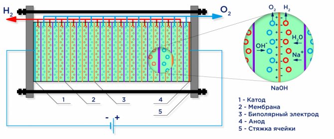
Electrolysis of water
Under the influence of an electric current, water is divided into its constituent molecules: hydrogen and oxygen. The negatively charged cathode attracts hydrogen cations, and the positively charged anode attracts OH - anions.
Demineralized water used in industrial electrolysis plants is itself a weak electrolyte, so strong electrolytes are added to it to increase the conductivity of electrical current. Electrolytes with a lower cation potential are often chosen to eliminate competition with hydrogen cations: KOH or NaOH. The electrochemical reaction occurring at the electrodes is as follows:
- Reaction at the anode: 2H2 O → O 2
+ 4H + + 4e − - release of oxygen; - Reaction at the cathode: 2H2O + 2e − → H 2
+ 2OH − - hydrogen evolution.
An industrial electrolyzer is assembled according to a bipolar circuit, where bipolar “intermediate” electrodes with different charges on the sides are placed between the main electrode and the cathode. On the side of the main anode, the intermediate electrode has a cathode side, on the cathode side - an anode side (see figure).
Next, in order to obtain pure hydrogen and oxygen, it is necessary to separate the gases formed at the electrodes, and for this, separation ion exchange membranes are used (see figure). The amount of hydrogen produced is twice as much as the oxygen produced and therefore the pressure in the hydrogen cavity rises twice as fast. To equalize the pressure in the cavities, a pressure equalizing membrane is used at the outlet of the electrolyzer, which prevents the transfer of hydrogen into the oxygen cavity through channels intended for circulation of the electrolyte.
This method is the most used method in industry and makes it possible to produce hydrogen gas with an efficiency of 50 to 70% with a productivity of up to 500 m 3 /hour with specific energy consumption of 4.5-5.5 N2m 3 /kWh.
ELECTROLYSIS ON TPE
At the moment, the most effective separation method is electrolysis using solid polymer electrolytes based on a perfluorinated ion exchange membrane.
This type of electrolyzer allows producing hydrogen with an efficiency of up to 90% and is the most environmentally friendly. Electrolyzers with TPE are 6-7 times more expensive than alkaline ones and therefore have not yet become widespread in industry.
source