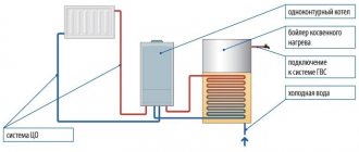
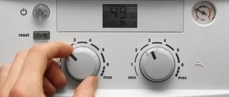
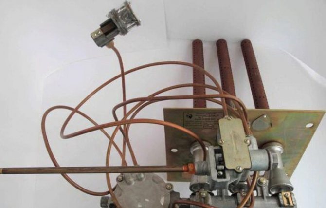
Why does a gas stove need a thermocouple?
The gas in the stove burner is ignited with matches, a manual piezo lighter or a built-in electric ignition. Then the flame should burn on its own without human intervention until the fuel is turned off by the valve.
However, often the fire on a gas hob or oven goes out as a result of a gust of wind or a splash of water from a boiling pan. And then, if there is no one nearby in the kitchen, methane (or propane) begins to flow into the room. As a result, when a certain concentration of gas is reached, a bang occurs with fire and destruction.
The thermocouple monitors the presence of an open flame in the burner, and if there is none, it shuts off the gas supply within half a minute to a minute to prevent a tragedy
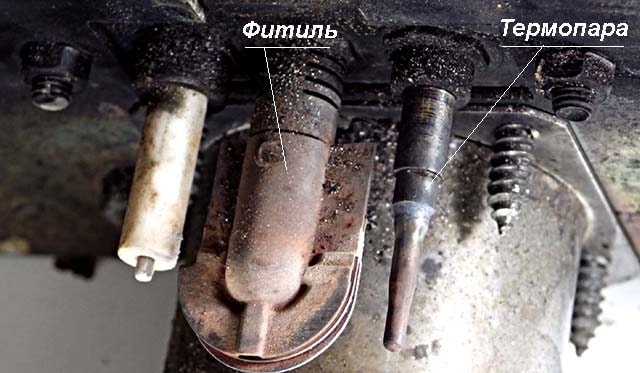
The working function of a thermocouple is to control the presence of a flame. While the gas is burning, the temperature at the tip of the control device reaches 800–1000 0C, and often higher. As a result, an EMF arises, which keeps the gas solenoid valve on the nozzle to the burner open. The burner is working.
However, when the open flame disappears, the thermocouple stops producing EMF to the electromagnet. The valve and fuel supply are shut off. As a result, the gas does not enter the kitchen without accumulating in it, which eliminates the possibility of a fire from such an emergency situation.
A thermocouple is a simple temperature sensor without any electronic devices inside. There is nothing to break in it. It can only burn out from prolonged use.
The following article, which is entirely devoted to this interesting issue, will introduce you to a complete set of sensors designed to control and safety the operation of a gas water heater.
Thermocouple burnout usually occurs only in gas boilers and boilers that operate continuously. In gas stoves, the gas control temperature sensors in question last 20–30 years before replacement.
Among the advantages of thermocouples:
- simplicity of the device and the absence of breaking mechanical or burned out electrical elements;
- the device is cheap - about 800–1500 rubles, depending on the model of the gas stove;
- long service life;
- high efficiency of flame temperature control;
- quick gas shut-off;
- ease of replacement, which you can do yourself.
The thermocouple has only one significant drawback - the difficulty of repairing the device. If the thermocouple sensor is faulty, it is easier to replace it with a new one.
To repair such a device, it is necessary to weld or solder two different metals at high temperature (about 1,300 0C). It is extremely difficult to achieve such conditions in everyday life at home. It is much easier to buy a new control unit for a gas stove as a replacement.
How does a thermocouple work in a gas boiler?
Since the open fire zone of heating devices is characterized by high temperatures, conventional measuring instruments and protection devices are not able to cope with their task and withstand extreme thermal loads.
The thermocouple is used to convert thermal energy into electric current for electromagnetic coils in gas boilers and serves as the main element of gas control protection.
It is made of several types of metal that are resistant to maximum temperatures inside the combustion chamber. The thermocouple works in conjunction with an automatic gas shut-off valve, which shuts off the gas supply to the fuel path.
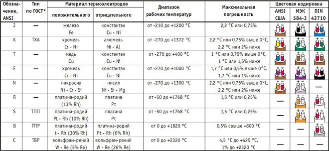
Types of thermocouples and their characteristics
Different alloys used to make thermocouples have different thermo-EMF coefficients. Depending on what metals the thermoelectrodes are made of, the following main types of thermocouples are distinguished:
- TPP13 – platinum-rhodium-platinum (type R);
- TPP10 – platinum-rhodium-platinum (type S);
- TPR – platinum-rhodium-platinum-rhodium (type B);
- TFA – iron-constantan (type J);
- TMKn – copper-constantan (type T);
- TNN – nichrosil-nisil (type N);
- THA – chromel-alumel (type K);
- THCn – chromel-constantan (type E);
- THC – chromel-copel (type L);
- TMK – copper-copel (type M);
- TSS – sil-silin (type I);
- TVR – tungsten rhenium (types A-1 – A-3).
Technical requirements for thermocouples are set by parameters defined by GOST 6616-94, and their NSC (nominal static conversion characteristics), optimal measurement ranges, established tolerance classes are regulated by IEC 62460 standards, and defined by GOST R 8.585-2001. Let us also note that the NSC in tungsten-rhenium thermocouples was absent from the IEC tables until 2008. To date, these standards do not define the characteristics of the Chromel-Kopel thermocouple, but their parameters are still regulated by GOST R 8.585-2001. Therefore, imported L-type thermocouples are not a complete analogue of the domestic THC product.
Thermal sensors can also be classified according to other criteria: by type of junction, number of sensitive elements.
Types of junctions
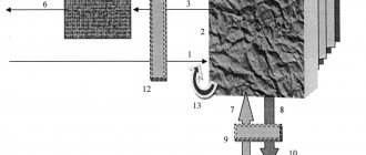
Depending on the purpose of the temperature sensor, the thermocouple junctions may have different configurations. There are single-element and two-element junctions. They can be either grounded to the body of the bulb or ungrounded. You can understand the diagrams of such structures from Figure 5.
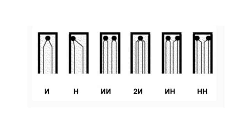
Rice. 5. Types of junctions
The letters indicate:
- And – one junction, isolated from the body;
- H – one junction connected to the body;
- AI – two junctions isolated from each other and from the housing;
- 2I – double junction, isolated from the housing;
- IN – two junctions, one of which is grounded;
- LV – two non-insulated junctions connected to the housing.
Grounding to the housing reduces the inertia of the thermocouple, which, in turn, increases the speed of the sensor and increases the accuracy of real-time measurements.
In order to reduce inertia, some models of thermoelectric converters leave a hot junction outside the protective flask.
Multipoint thermocouples
It is often necessary to measure temperature at different points simultaneously. Multipoint thermocouples solve this problem: they record temperature data along the axis of the transmitter. This need arises in the chemical and petrochemical industries, where it is necessary to obtain information about the temperature distribution in reactors, fractionation columns and other vessels intended for chemical processing of liquids.
Multipoint temperature measuring transducers increase efficiency and do not require complex maintenance. The number of data collection points can reach up to 60. In this case, only one flask and one entry point into the installation are used.
Thermocouple comparison table
Above we looked at the types of thermoelectric converters. The reader most likely has a reasonable question: Why are there so many types of thermocouples?
The fact is that the measurement accuracy declared by the manufacturer is only possible in a certain temperature range. It is in this range that the manufacturer guarantees the linear characteristics of its product. In other ranges, the dependence of voltage on temperature may be nonlinear, and this will certainly affect the accuracy. It should be taken into account that materials have different degrees of fusibility, so there is a limiting operating temperature for them.
To compare thermocouples, tables have been compiled that display the main parameters of measuring transducers. As an example, we present one of the table options for comparing common thermocouples.
Table 1.
| Thermocouple type | K | J | N | R | S | B | T | E |
| Positive electrode material | Cr—Ni | Fe | Ni—Cr—Si | Pt—Rh (13% Rh) | Pt—Rh (10% Rh) | Pt—Rh (30% Rh) | Cu | Cr—Ni |
| Negative electrode material | Ni—Al | Cu—Ni | Ni—Si—Mg | Pt | Pt | Pt—Rh (6% Rh | Cu—Ni | Cu—Ni |
| Temperature coefficient | 40…41 | 55.2 | 68 | |||||
| Operating temperature range, ºC | 0 to +1100 | 0 to +700 | 0 to +1100 | 0 to +1600 | 0 to 1600 | +200 to +1700 | −185 to +300 | 0 to +800 |
| Limit temperature values, ºС | −180; +1300 | −180; +800 | −270; +1300 | – 50; +1600 | −50; +1750 | −250; +400 | −40; +900 | |
| Accuracy class 1, in the corresponding temperature range, (°C) | ±1.5 -40 °C to 375 °C | ±1.5 -40 °C to 375 °C | ±1.5 -40 °C to 375 °C | ±1.0 from 0 °C to 1100 °C | ±1.0 from 0 °C to 1100 °C | ±0.5 -40 °C to 125 °C | ±1.5 -40 °C to 375 °C | |
| ±0.004×T from 375 °C to 1000 °C | ±0.004×T from 375 °C to 750 °C | ±0.004×T from 375 °C to 1000 °C | ±[1 + 0.003×(T − 1100)] 1100 °C to 1600 °C | ±[1 + 0.003×(T − 1100)] 1100 °C to 1600 ° | ±0.004×T from 125 °C to 350 °C | ±0.004×T from 375 °C to 800 °C | ||
| Accuracy class 2 in the corresponding temperature range, (°C) | ±2.5 -40 °C to 333 °C | ±2.5 -40 °C to 333 °C | ±2.5 -40 °C to 333 °C | ±1.5 from 0 °C to 600 °C | ±1.5 from 0 °C to 600 °C | ±0.0025×T from 600 °C to 1700 °C | ±1.0 -40 °C to 133 °C | ±2.5 -40 °C to 333 °C |
| ±0.0075×T from 333 °C to 1200 °C | ±0, T from 333 °C to 750 °C | ±0.0075×T from 333 °C to 1200 °C | ±0.0025×T from 600 °C to 1600 °C | ±0.0025×T from 600 °C to 1600 °C | ±0.0075×T from 133 °C to 350 °C | ±0.0075×T from 333 °C to 900 °C | ||
| Color coding of terminals according to IEC | Green - white | Black White | Lilac - white | Orange - white | Orange - white | Absent | Brown - white | Purple - white |
Plate thermocouple malfunction
If the functionality of the flame ignition is impaired, the thermocouple should be checked. First turn off the gas supply and power supply.
In some situations, the problem can be resolved by cleaning. It is not recommended to use excessive mechanical force to avoid damaging the serviceable part. The performance is checked with a multimeter. When the working area is heated, the appearance of voltage in the measurement range of 10-60 mV is recorded.
For replacement, purchase products recommended by the manufacturer of household appliances.
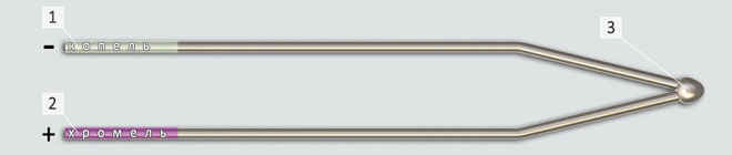
Design and principle of operation
It is known that in a closed circuit, which consists of two conductors of different metals (for example, chromel and copel), a thermoelectromotive force (EMF) arises, provided that their hot and cold junctions have different temperatures (Seebeck effect). The value of the EMF depends on the materials of the conductors, the temperatures of their cold and hot junctions.
Typically, the voltage of a household thermocouple is in the range of 20-60 millivolts (mV), which is enough to open the gas valve, but, of course, not enough to operate complex automation and other modules that already require an electrical connection.
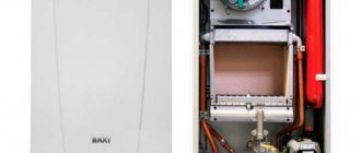
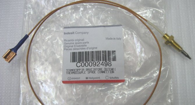
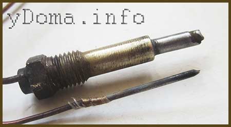
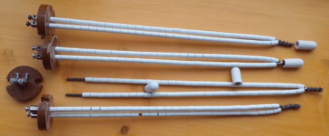
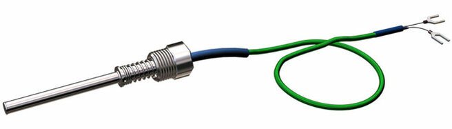
This is what a standard thermocouple looks like in the photo.
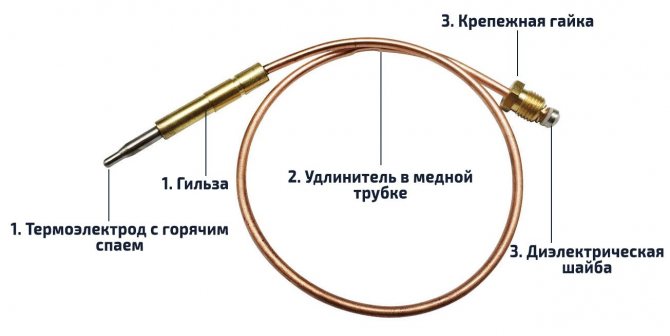
The module is not limited to a pair of junctions, but the thermocouple device is quite simple and understandable:
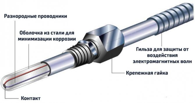
- The sleeve, inside of which there are thermoelectrodes with the “hot” junction of the conductors, is what is attached to the burner module of the boiler, next to the pilot burner (igniter).
- An extension cord, protected by a copper tube from external influence of electromagnetic fields, is used to connect the working part (hot junction) with the electromagnetic gas valve.
- A dielectric washer with a “cold” junction, it is this that is inserted into the socket of the gas solenoid valve.
Most often, thermocouples of domestic gas boilers use junctions made of chromel and alumel (TCA), chromel and copel (TCC), and iron and constantan (TLC). All alloys used, their markings and characteristics are listed in the table below.
| Thermocouple type (European classification) | Junction conductor materials | Russian markings | Temperature range, °C |
| K | chromel-alumel | THA | -200 – 1 300 |
| L | chromel-copel | THC | -200 – 850 |
| J | iron-constantan | TZHK | -100 – 1 200 |
| N | nikhrosil-nisil | TNN | -200 – 1 300 |
| T | copper-constantan | TMKn | -200 – 400 |
| E | chromel-constantan | THKn | 0 – 600 |
| S | platinum-rhodium-platinum | TPP10 | 0 – 1 700 |
How does a thermoelectric thermometer work as part of a gas boiler?
The operating principle of a thermocouple in a gas boiler is the same everywhere:
- First, a person mechanically opens the gas supply valve by holding the solenoid valve button for 15-30 seconds.
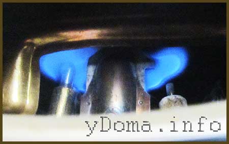
- Then the piezo ignition button is pressed once, a spark appears and the pilot burner lights up.
- The magnetic valve button is held down for another 30-60 seconds until the working junction of the thermocouple, located next to the igniter, heats up and produces the required voltage.
- After 30-60 seconds, the solenoid valve button is released, but combustion continues as the heated thermocouple produces enough voltage to hold the gas valve open. The boiler operates normally, without human intervention.
- Once combustion stops, the flame no longer heats the thermocouple, causing the voltage to be insufficient to hold the gas solenoid valve open and it closes, stopping the flow of gas.
What metals are thermocouple conductors made of?
All thermocouples are created from certain alloys of noble and base metals that have a constant, repeatable relationship between temperature difference and voltage.
We recommend: Chimney cleaning: how to clean a chimney from soot using traditional and modern methods. Each group of alloys is used for specific temperature ranges and is used in installed heating devices.
There are three main types of thermocouples most commonly used in boiler markets:
- Type E. Made from chromel and constant plates. It is highly reliable. Has the factory marking THKn. The operating temperature range is from 0 to +600°C.
- Type J. Similar to the previous thermocouple, but iron is used instead of chromel. The device is practically not inferior in functions to type E, but the price is much lower. Labeling: TFA. The temperature range varies from -100 to +1200°C.
- Type K. The most common and widely used type of thermocouple. Marking: THA. The composition contains plates made of chromel and aluminum. Operating temperatures range from – 200 to +1350°C. Such devices are quite sensitive to the slightest temperature changes, but at the same time they are highly dependent on the environment. For example, carbon dioxide can significantly reduce the life of a device and cause premature repairs.
How to check and replace a thermocouple
The main sign of a malfunctioning flame sensor is that the wick goes out simultaneously with the release of the button. Sometimes the problem manifests itself differently - the light on the igniter remains, but after igniting the main burner, the fuel supply is shut off again and the boiler goes out completely. Reasons for such problems:
- the thermal electrode is covered with soot and does not warm up well, causing the voltage in the circuit to drop below the minimum;
- burnout of the meter body;
- contact failure at the hot junction point;
- the fastening nut has been unscrewed, the working rod is skewed and is poorly heated by the igniter;
- the traction sensor has become unusable or its electrical circuit has broken.
The electrode heated by the igniter must be periodically cleaned of carbon deposits. The problem is that the contamination of the part is hard to see from the outside; you have to remove the bar or the entire panel with the burner
Clarification. A malfunction of the draft sensor causes similar symptoms, since this “limit switch” is connected in series with the thermocouple (in an open circuit). To eliminate the influence of the sensor, temporarily short-circuit its wires.
For diagnostics, you will need a multimeter or other device capable of measuring low voltage (up to 100 mV). How the check is performed:
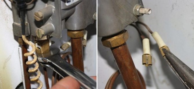
- Close the gas supply to the heat generator or instantaneous water heater using the tap located on the supply pipe. Remove the casing or front panel of the unit.
- Using open-end wrenches, unscrew the nuts securing the thermoelectrode and connecting tube. Remove the flame sensor.
- Carefully inspect the working electrode, clean it of soot with a brush and rag. If burnouts are detected during a visual inspection, the thermocouple must unconditionally be replaced.
- Moving to the kitchen, light the gas stove burner. Connect the multimeter clamps to the center terminal and the copper tube. Set the lowest measurement limit – 0.1 or 1 V.
- Heat the thermoelement with a gas stove burner while observing the voltmeter readings.
The main condition: a working thermocouple for the boiler must produce a voltage of at least 0.02 volts. If the device shows zeros, the voltage fluctuates or does not exceed 20 mV, the element needs to be changed. Modern sensors cannot be repaired by re-soldering.
Advice. When buying a new thermocouple, always be guided by the brand and specific model of the boiler, so as not to get confused in the markings and designations.
If you don’t want to remove the element ahead of time, diagnostics can be performed directly on the boiler. After unscrewing the nut, disconnect the thermocouple tube from the automation and connect the multimeter as described above. While holding the key, light the igniter and take readings from the device. Disadvantage of the method: the impossibility of visual inspection and cleaning of the electrode from soot.
How to weld a burnt thermocouple of a geyser
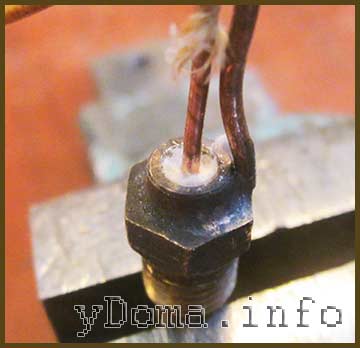
Due to professional needs, I periodically have to manufacture thermocouples for devices for maintaining a given temperature in drying cabinets and in equipment for annealing twisted magnetic cores for transformers at a temperature of 800°C. Therefore, when manufacturing the next thermocouple, I decided to try to restore the functionality of a burnt thermocouple from a gas water heater by welding.
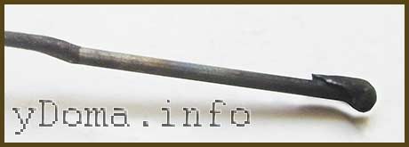
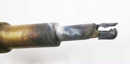
The central wire of the thermocouple was welded to the copper wire of the electrical wiring and had a length of about 5 cm. In the photograph, the soldering site is clearly visible on the left. This length of wire would be enough for several repairs.
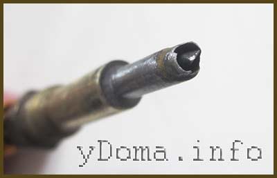
The tubular conductor of the thermocouple, about a centimeter long, was completely burnt out, but a part of it with a thicker wall remained.
The previous welding site was removed from the central conductor, and the thermocouple parts were cleaned of soot and deposits using fine sandpaper.
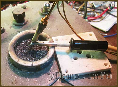
The central conductor was inserted into the base of the thermocouple so that its end protruded one millimeter. Welding was carried out on a special installation, the device and circuit of which I will describe below, for about four seconds at a voltage of 80 V and a current of about 5 A.
We recommend: Uninterruptible power supply (UPB) for a solid fuel boiler
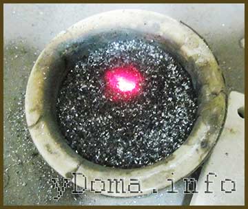
I did not make a video recording of the thermocouple welding process for fear of damaging the camera from a bright arc, but I took a photo of hot graphite powder a couple of seconds after the welding was completed.
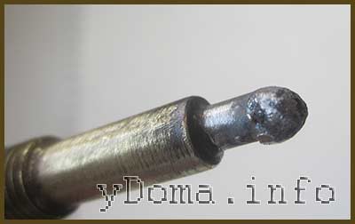
The thermocouple junction turned out, contrary to my expectations, of excellent quality and beautiful shape. I became confident that I had not started repairing the thermocouple in vain.
To prevent the central conductor of the thermocouple from shorting to its body, fiberglass wool was tightly packed into the gap. Asbestos is also good for these purposes.
To ensure that the thermocouple was working, it was heated with a soldering iron to a temperature of about 140°C.
The multimeter recorded the EMF generated by the thermocouple as 5.95 mV, which confirmed the serviceability of the thermocouple. It remains to check the functionality of the thermocouple in the gas column.
Although the thermocouple became a centimeter shorter, its length was still quite enough for the junction to be in the igniter flame. The restored thermocouple has been working flawlessly in the gas water heater for several months now, and, I believe, will work much longer than a factory-made thermocouple, since the junction point has become much more massive.
Advantages and disadvantages
Like any device, thermocouples have both advantages and disadvantages. Among the advantages of the devices are their low cost, which is due to a fairly simple design, and a long service life. The durability of the devices is explained by the absence of complex components and moving elements subject to friction. An important advantage is the wide range of measured temperatures, as well as easy installation and dismantling of the device. The versatility of thermocouples cannot be ignored, allowing the device to be used both as a flame control sensor and as a thermometer.
Disadvantages include the voltage limit, which is limited to 50 mV. This is one of the reasons for errors in readings that occur when measuring temperatures. The lack of a linear relationship between temperature values and potential difference is also a disadvantage of the device. In addition, the part cannot be repaired, and if it fails, it is replaced with a new one. However, sometimes the thermocouple stops working due to poor contact. To resume boiler operation, you need to remove the thermocouple, clean the conductors and reinstall the device.
Connection, testing and troubleshooting
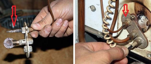
One of the common malfunctions of gas boilers is as follows: you press the gas supply button, light the igniter, hold it for the required 30 seconds, release it and the burner immediately goes out. One of the reasons that can lead to this result is a faulty thermocouple or its poor contact with the solenoid valve.
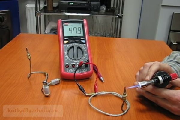
Photo 5: Connecting and checking the thermocouple on the measuring device
You can fix this problem yourself without resorting to the services of a specialist. To do this you need to follow these steps:
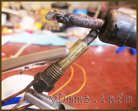
- Using a wrench, unscrew the clamping nut that holds the thermocouple in contact with the solenoid valve and remove its end.
- We inspect the connector for the presence of various oxides and contaminants. If necessary, use fine sandpaper to carefully clean the contact area.
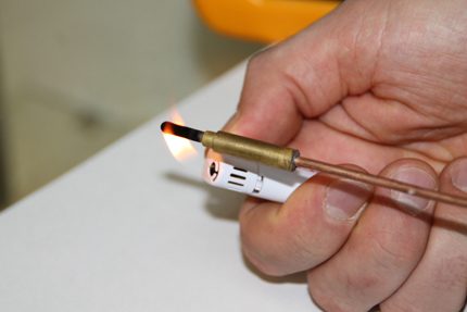
- Next, you should check the thermocouple with a multimeter. To do this, we connect one end to the measuring device, and heat the other with a manual gas burner. The voltage at the ends of a working thermocouple should be about 50 mV.
- If all indicators are normal, you should put everything back together and try to start the boiler.
If the problem remains, most likely the solenoid valve itself is faulty or the contact between it and the thermocouple is still poor. If the valve is in good condition, you should re-clean the connection and try to find a position of the clamping nut at which good contact is achieved.
Useful:
A compensation wire is usually used to connect thermocouples to measuring instruments. In this cable, the cores are made of the same material as the sensor itself. This can significantly reduce measurement error.
If the thermocouple fails, you need to buy a new one. There are many different manufacturers producing these sensors on the Russian market: Arbat, AKGV, AOGV (Zhukovsky plant), Honeywell. Prices for different types range from 600 to 2000 rubles.
For more information on how to repair a thermocouple in a gas boiler yourself at home, see the following video:
Connection and testing
The thermocouple must be connected using electrodes (wires) made of the same material as the thermocouple being connected.
Or metal wires can be used, which have characteristics similar to those of the electrodes on the thermocouple itself.
Before connecting thermocouples for heating boilers, it is important to strip the ends of the wires to remove oxides that affect the accuracy of the measurements. And during installation, it is important to ensure that the fuel outlet and supply pipes are lowered straight down.
If the thermocouple is broken, as a rule, it is no longer possible to restore it, so it is important to know how to check the thermocouple with a multimeter on a gas boiler.
The working thermocouple should operate after 10-30 seconds of heating
To check its functionality, just connect one end to a multimeter - a measuring sensor, and heat the other end using a gas burner or lighter.
A combined electrical measuring instrument, which can be digital and analog, combines several functions (at least the functions of a voltmeter, ohmmeter, ammeter). Multimeter
The working thermocouple should have a voltage around 50 mV.
If a thermocouple malfunction is confirmed, you can replace it yourself.
Types and types of thermocouples
The variety of thermocouples is explained by the different combinations of metal alloys used. The selection of a thermocouple is carried out depending on the industry and the required temperature range.
Chromel-alumel thermocouple (TCA)
Positive electrode: Chromel alloy (90% Ni, 10% Cr). Negative electrode: alumel alloy (95% Ni, 2% Mn, 2% Al, 1% Si).
Insulation material: porcelain, quartz, metal oxides, etc.
Temperature range from -200°C to 1300°C for short-term and 1100°C for long-term heating.
Working environment: inert, oxidizing (O2=2-3% or completely excluded), dry hydrogen, short-term vacuum. In a reducing or redox atmosphere in the presence of a protective cover.
Disadvantages: ease of deformation, reversible instability of thermo-emf.
There may be cases of corrosion and embrittlement of alumel in the presence of traces of sulfur in the atmosphere and chromel in a weakly oxidizing environment a).
Chromel-Copel thermocouple (TCC)
Positive electrode: Chromel alloy (90% Ni, 10% Cr). Negative electrode: Copel alloy (54.5% Cu, 43% Ni, 2% Fe, 0.5% Mn).
Temperature range from -253°C to 800°C for long-term heating and 1100°C for short-term heating.
Working environment: inert and oxidizing, short-term vacuum.
Disadvantages: deformation of the thermoelectrode.
Evaporation of chromium is possible during prolonged vacuum; reaction with an atmosphere containing sulfur, chromium, fluorine.
Iron-constantan thermocouple (ILC)
Positive electrode: commercially pure iron (low carbon steel). Negative electrode: constantan alloy (59% Cu, 39-41% Ni, 1-2% Mn).
Used for measurements in reducing, inert environments and vacuum. Temperature from -203°C to 750°C for long-term and 1100°C for short-term heating.
The application is based on the combined measurement of positive and negative temperatures. It is unprofitable to use only for negative temperatures.
Disadvantages: deformation of the thermoelectrode, low corrosion resistance.
Changes in the physicochemical properties of iron around 700°C and 900°C. Interacts with sulfur and water vapor to form corrosion.
Tungsten-rhenium thermocouple (TVR)
Positive electrode: alloys BP5 (95% W, 5% Rh)/VAR5 (BP5 with silicon-alkali and aluminum additive)/BP10 (90% W, 10% Rh). Negative electrode: BP20 alloys (80% W, 20% Rh).
Insulation: ceramics made from chemically pure metal oxides.
Mechanical strength, heat resistance, low sensitivity to dirt, and ease of manufacture are noted.
Temperature measurement from 1800°C to 3000°C, lower limit – 1300°C. Measurements are carried out in an inert gas, dry hydrogen or vacuum environment. In oxidizing environments only for measurements in fast processes.
Disadvantages: poor reproducibility of thermo-EMF, its instability when irradiated, inconsistent sensitivity in the temperature range.
Tungsten-molybdenum thermocouple (TM)
Positive electrode: tungsten (technically pure). Negative electrode: molybdenum (technically pure).
Insulation: alumina ceramic, protected with quartz tips.
Inert, hydrogen or vacuum environment. It is possible to carry out short-term measurements in oxidizing environments in the presence of insulation. The range of measured temperatures is 1400-1800°C, the maximum operating temperature is about 2400°C.
Disadvantages: poor reproducibility and sensitivity of thermo-EMF, polarity inversion, embrittlement at high temperatures.
Platinum-rhodium-platinum thermocouples (TPP)
Positive electrode: platinum rhodium (Pt with 10% or 13% Rh). Negative electrode: platinum.
Insulation: quartz, porcelain (regular and fireproof). Up to 1400°C - ceramics with a high content of Al2O3, above 1400°C - ceramics made from chemically pure Al2O3.
The maximum operating temperature is 1400°C for a long time, 1600°C for a short time. Low temperatures are usually not measured.
Working environment: oxidizing and inert, reducing in the presence of protection.
Disadvantages: high cost, instability when irradiated, high sensitivity to contamination (especially the platinum electrode), growth of metal grains at high temperatures.
Platinum-rhodium-platinum-rhodium (PPR) thermocouples
Positive electrode: Pt alloy with 30% Rh. Negative electrode: Pt alloy with 6% Rh.
Features of thermocouple for muffle furnace
A thermocouple for an electric furnace is a part that allows you to measure temperature in various, including extreme conditions. An element is made of two conductors soldered at one point. The wire is made of special alloys. When heated, the base generates electricity. The higher the temperature in the chamber, the more millivolts are generated.
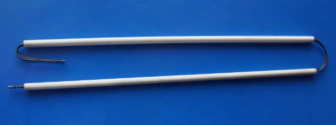
The thermocouple is made of two conductors, which are made of different alloys. They are connected to each other only on one side
Thermocouples are produced in different designs, the following may differ:
- Electrode thickness.
- Wire material.
- Outer shell.
- Terminal block, etc.
The thermocouple shell is made of both specialized alloys and ceramics
Design features of the thermocouple
Before making a thermocouple, make sure that the chosen method of execution is suitable for the intended production conditions. The type of construction is directly reflected in:
- Maximum operating temperature.
- Application environment.
- Operational life.
Of the design features, it is worth focusing on:
- Connection . The electrode tips are twisted together and fastened at one point. For this purpose, welding or soldering is used. Refractory wire is often connected by twisting without welding. In this case, docking is possible only at the working junction. The length of the wires must be protected from interaction.
- Isolation . How to insulate the electrodes depends on the highest temperature limit. For maximum temperatures from +100°C to +120°C, any method can be used, including air. If the mark reaches +1300°C, porcelain single- and double-channel tubes are used. Pyrometric ceramics are not suitable for higher temperatures; they may soften. In this case, aluminum oxide tubes that can withstand up to +1950°C are recommended. For temperatures from +2000°C, insulation from magnesium or beryllium oxide, as well as thorium or zirconium dioxide is used.
- External protection . The work environment must be taken into account. The thermocouple is protected using a metal, ceramic or metal-ceramic sheath tube with a closed end. Thanks to it, the mechanical resistance of the element and its tightness are ensured.
When creating an electric furnace for industrial purposes, it is important to choose the right thermocouple protective material. Make sure it can withstand prolonged exposure to extreme temperatures. The degree of resistance to chemical environments, gas tightness and thermal conductivity is taken into account
Thermocouple junction
Most thermocouples are designed with only one junction. However, when a thermocouple is connected to an electrical circuit, another junction may form at its connection points.
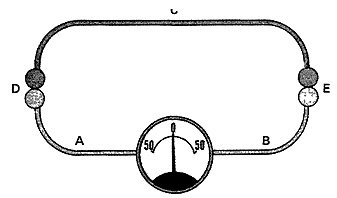
Thermocouple circuit
The circuit shown in the figure consists of three wires labeled A, B, and C. The wires are twisted together and labeled D and E. A junction is an additional junction that is formed when a thermocouple is connected to the circuit. This junction is called the free (cold) junction of the thermocouple. Junction E is the working (hot) junction. There is a measuring device in the circuit that measures the difference in voltage values at two junctions.
The two junctions are connected in such a way that their voltage opposes each other. Thus, the same voltage value is generated at both junctions and the device readings will be zero. Since there is a directly proportional relationship between temperature and the amount of voltage generated by a thermocouple junction, two junctions will generate the same voltage values when the temperature across them is the same.
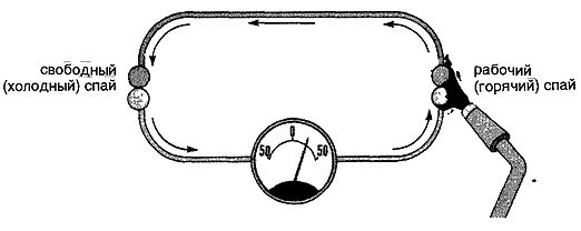
Effect of heating one thermocouple junction
When the thermocouple junction heats up, the voltage increases in direct proportion. The flow of electrons from the heated junction flows through the other junction, through the measuring instrument and back to the hot junction. The device shows the voltage difference between two junctions. Voltage difference between two junctions. The voltage difference shown by the meter is converted into temperature readings, either using a table or directly displayed on a scale that is calibrated in degrees.
Thermocouple cold junction
The cold junction is often the point where the free ends of the thermocouple wires are connected to the meter.
Since the thermocouple circuit meter is actually measuring the voltage difference between the two junctions, the cold junction voltage must be kept as constant as possible. By maintaining the voltage at the cold junction at a constant level, we thereby ensure that a deviation in the readings of the measuring device indicates a change in the temperature at the working junction.
If the temperature around the cold junction changes, the voltage across the cold junction will also change. As a result, the voltage at the cold junction will change. And as a result, the difference in voltage at the two junctions will also change, which will ultimately lead to inaccurate temperature readings.
In order to keep the cold junction temperature constant, many thermocouples use compensating resistors. The resistor is in the same location as the cold junction, so the temperature affects the junction and the resistor at the same time.
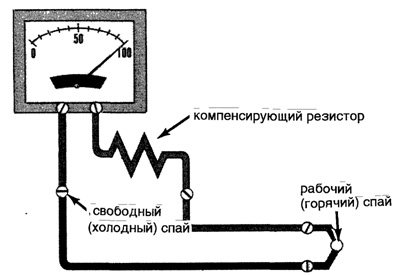
Thermocouple circuit with compensating resistor
Working junction of thermocouple (hot)
A service junction is a junction that is exposed to the process whose temperature is being measured. Due to the fact that the voltage generated by a thermocouple is directly proportional to its temperature, when the working junction is heated, it generates more voltage, and when cooled, less.
Checking the thermocouple of a home geyser
Long-term operation of a home geyser fully allows for such a moment when the thermocouple fails. In this case, it is necessary to check the functioning of the system and, accordingly, check the control sensor itself.
Of course, not all owners of gas equipment are able to perform such work. And from a safety point of view, the best solution would be to contact the gas company to solve this problem.
But at the same time, situations may be different, including the impossibility of contacting specialists for some reason. Then the only option left is to try to do the work yourself.
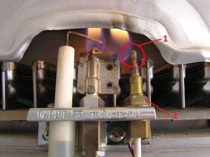
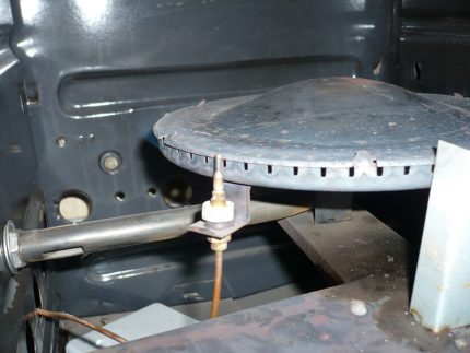
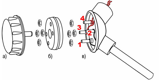
The picture shows one of the options for an installed thermocouple that needs to be checked: 1 – the directly hot area of the sensor, which is most often susceptible to destruction; 2 – fastening nut, which must be unscrewed for dismantling; The same nut can be used on the other end of the thermocouple
In this scenario, a user inexperienced in gas matters is interested in how to check the thermocouple on a gas boiler using a tester - a common electrical and electronics diagnostic device. Let's try to reveal this technological point in order to make the task easier.
We recommend: Hydrogen heating boilers: why you should not choose a hydrogen fuel boiler for heating a private home, review and comparison of efficiency and cost-effectiveness, the best models and their prices
Stage #1 - preparation for testing by a tester
To begin with, let us remind you that a tester is a measuring device - pointer or digital, with which it is possible to measure:
- resistance;
- voltage value (AC and DC);
- current strength (AC, DC).
The measured values marked are sort of basic. Moreover, modern testers are able to check a number of other parameters, for example, inductance or capacitance.
But taking into account the principle of operation of the thermocouple of a household gas boiler, the voltage measurement mode in the millivolt range is quite sufficient.
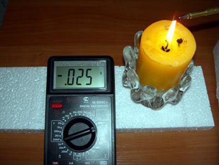
The procedure for testing a thermocouple using a measuring device and a simple heating element - a paraffin candle. As can be seen from the tester readings (25 mV), the gas burner flame control sensor is working properly
In addition to the measuring instrument (tester), the installer will need another fairly simple tool - a heating source. It is better if such a source has the ability to emit an open flame. Therefore, the best option here would be to use a regular paraffin candle.
Stage #2 - visual inspection for defects
The procedure for testing the flame control sensor is simple. However, before proceeding with the hot test, it is recommended to carefully examine the thermocouple visually from the outside.
When inspecting the area of the junction and the descending rod, physical defects of the metal, including burnout areas, should not be visible on the surface.
Stage #3 - testing the sensor's performance
After completing the visual inspection, you can proceed directly to the hot test. To do this, the junction area and the downward section of the gas column thermocouple rod are placed above the candle wick.
Next, a measuring device (tester) is connected to the terminal ends of the thermocouple, after which the candle is lit. The generated potential is observed on the working scale of the measuring device.
In fact, to check the functionality of the sensor, it is permissible to use any suitable heating source, for example, a household lighter. True, depending on the power of the heating source, the readings on the tester may be below normal or, conversely, above normal
The absence of any electrical potential readings clearly indicates a sensor malfunction. In case of partial defects, chaotic (unstable) readings of units of millivolts may be observed on the measuring device. If the geyser sensor is working properly, a stable value equal to tens of millivolts (20-30 mV) is usually recorded on the device.
Moreover, as the thermocouple body is heated by a candle flame, the readings on the instrument scale change slightly upward. If the candle flame is extinguished, the tester readings will tend to zero as the rod body and junction area cools. That's all. With this development of events, the thermocouple, as being in good working order, can be safely placed at the site of action.
Measurement speed
The performance is determined by the ability of the primary converter to quickly respond to temperature surges and the subsequent flow of input signals from the measuring device.
Factors that increase performance:
- Correct installation and calculation of the length of the primary converter;
- When using a converter with a protective sleeve, it is necessary to reduce the mass of the assembly by selecting a smaller diameter of the sleeves;
- Minimizing the air gap between the primary converter and the protective sleeve;
- Using a spring-loaded primary converter and filling the voids in the sleeve with a heat-conducting filler;
- A fast moving or denser medium (liquid).
Features of the industrial thermocouple device
Thermal sensors are made mostly from base metals. They are protected from the influence of the external environment by a pipe with a flange that serves to mount the device. Protective fittings protect conductors from the influence of aggressive environments and are made without seams. The material is ordinary (up to 600ºС) or stainless steel (up to 1100ºС). Thermoelectrodes are insulated from each other with asbestos, porcelain tubes or ceramic beads.
If the terminal is located close, then the thermocouple wires are connected to it directly, without additional connectors. When the measuring device is located at a distance, when it is connected to the circuit, the free ends of the thermocouple are placed in a cast head attached to a protective tube. Inside there are brass terminal blocks on a porcelain base for connecting compensation wires, made of the same materials as thermoelectrodes, but not having precise and strictly controlled characteristics. They are less expensive and thicker. They are inserted into the head through a fitting with an asbestos gasket. Ceramics serves to equalize the temperature at all joints. There is a threaded protective cap with an airtight seal on top.
Crimp terminals should not be installed on wires as they may impair the accuracy of the readings. A ring is made from wire and clamped under a screw.
Correction of temperature changes at the terminals can be done electronically, which increases the accuracy of measurements.
Measurement error
The correctness of temperature readings obtained using a thermocouple depends on the material of the contact group, as well as external factors. The latter include pressure, background radiation or other reasons that can affect the physical and chemical properties of the metals from which the contacts are made.
consists of the following components:
- random error caused by the manufacturing features of the thermocouple;
- error caused by a violation of the temperature regime of the “cold” contact;
- error caused by external interference;
- error of control equipment.