Description of types of waste heat boilers
Waste heat boilers use thermal energy from waste gases
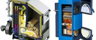
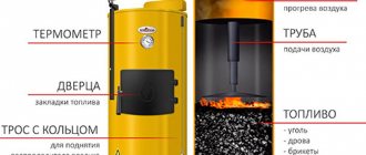
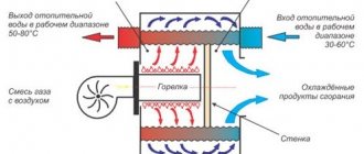
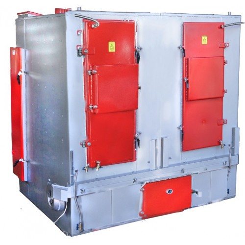
The operation of heat exchange units is based on the transfer of energy contained in hot gas masses to a liquid coolant. A recovery boiler is usually not equipped with a burner, since its design does not involve heating and combustion of fuel resources. But it contains an incandescent electrode and a block that ensures artificial movement of gas along the internal paths of the boiler unit. The devices differ in a number of characteristics: they are single- and double-circuit, with different dimensions of the heating tank.
Depending on the temperature of the exhaust gases, units can be divided into those operating at low and high temperatures. The first category includes indicators up to 900 °C, the second – those exceeding 1000 °C.
Based on the operating principle, waste heat boilers can be divided into two classes. Steam units are used to generate hot steam for heating or industrial use. Water heating devices take gases that leave the installation and transfer their heat to water. The latter can be used for heating or other purposes.
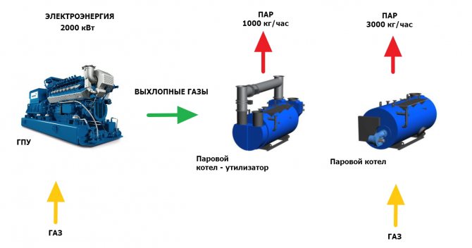
Steam devices and boilers designed to heat water can be equipped with a combustion chamber. Since a lot of energy is generated by recycling masses of gases that would otherwise be released into the atmosphere, such boilers are sometimes used to produce electricity. There are models that are not equipped with a firebox. In such devices, gases directly act on a heat exchanger with liquid or steam.
All structural elements in which combustion processes take place are made of fire-resistant materials.
Waste heat boilers CCGT
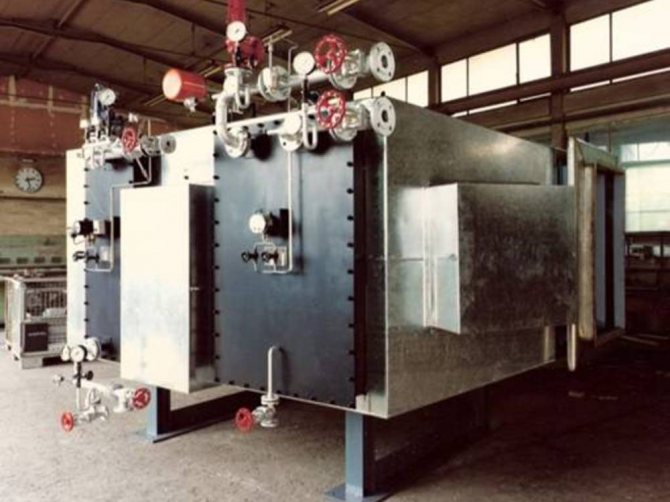
As a rule, all recyclers consist of the same basic elements, have a similar design and a similar principle of operation.
The boiler consists of a heating chamber, metal chambers for evaporating water, and a smoke collection unit. This is necessary to accumulate a gas cloud and press it into a receiver - a special storage device designed for a pressure of 5 atmospheres.
The operating principle consists of three successive stages:
- waste or gas enters the smoke collection systems forcibly. As a rule, smoke is sucked in by back pressure compressors and enters receivers equipped with a dosage and supply system. The use of receivers contributes to the uninterrupted operation of boilers;
- exhaust smoke is supplied from the storage tank to the combustion chamber, where it is burned by hot electrodes, generating huge amounts of thermal energy;
- Water evaporating in the chambers forms steam, which can act on the impellers of generator turbines or produce mechanical energy for moving devices or mechanisms.
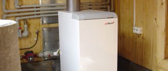
Protherm wall-mounted electric boilers are an alternative to gas heating with a number of undeniable advantages!
Read more about the door deaerator here.
Such boilers are not equipped with a separate combustion chamber like other heating devices using solid fuel or liquid raw materials.
The use of a separate chamber is impractical, since smoke or exhaust gas is a light raw material, prone to leaks, which is immediately burned. All waste heat recovery boilers operate on this principle.
Equipment configuration
In the basic configuration, the boiler units are equipped with a sufficient number of functional blocks. It necessarily includes a pump group, insulating devices, and a control panel.
Reorientation of a production enterprise or its development of new areas of activity may require additional technical devices. It may include the following elements:
- protective devices: heat-resistant shielding, safety blocks, shut-off valves, hanging parts;
- pump equipment;
- devices providing ventilation and injection of air masses.
Some multi-component systems also use reinforcement elements from the plumber's arsenal. They are needed for the design of various types of heat exchange devices.
In some situations, it is advisable to purchase a source of uninterrupted electricity. The design of a number of models provides the possibility of connecting a burner.
Specifications
The full use of gas waste allows boilers to have high efficiency indicators. For devices running on liquid or solid fuel, they are significantly smaller. However, if the heat exchange surfaces are heavily clogged, the efficiency of the unit will decrease. These parts of the structure can be cleaned by washing with water or blowing with steam. Vibration cleaning technology is also used.
Different industries use different types of boilers at certain stages of the production cycle. They differ in the number of steam generation registers, power parameters, circulation circuits used, and demands on the quality of the coolant.
How efficiently the unit will operate depends on the type of supply, the amount of gas masses and their temperature. The volumes of waste discharged differ from industry to industry. The largest amount is formed during oil refining and metallurgy. Charge gas is specific to the latter. The presence of metal scale is favorable for combustion of gas fuel.
Description of varieties
Depending on the temperature of the exhaust gases, waste heat boilers are divided into the following types: low-temperature (convection 900 °C) and high-temperature (over 1000 °C) .
According to the principle of operation, there are the following types: steam (with or without a steam collector) and hot water.
The waste heat boiler (hot water and steam) is of two types by design:
- Without combustion chamber . In such a device, the operating principle is based on the direct effect of waste gases on a heat exchanger with water or steam and the production of heating and hot water.
- With combustion chamber . The waste heat boiler recycles exhaust gases, burns them and receives more energy to heat the coolant, this is the principle of its operation. Such modifications of units have sufficient energy, so in some cases they are used to generate electricity .
Advantages and disadvantages
HRSG reduces energy emissions
The devices under consideration differ from other types of boiler units by the absence of the need for additional fuel. The utilizer operates only on gas waste. This allows you to use fuel much more efficiently, as well as reduce the cost of cleaning exhausts. In addition, the use of such boilers in enterprises has a positive effect on the environment. Energy emissions are significantly reduced. By reducing the volume of burned hydrocarbon-containing fuel, significantly less greenhouse gases are released into the atmosphere. An energy-saving production cycle reduces enterprise costs.
Cold parts of the unit are subject to corrosion. The efficiency of using a heat exchanger depends on the temperature to which the generated gases are heated.
RECOVERY BOILERS. BASIC INFORMATION
The main manufacturer of waste heat boilers is the Belgorod Boiler Plant, which, together with NPO TsKTI, has developed more than 200 designs of various types of waste heat boilers.
Among the various types of waste heat boilers, gas-tube boilers are classified into a separate group. Marking of gas-tube boilers: G - horizontal, V - vertical, B - with an external drum separator, I - with an upstream evaporation surface, P - with a steam superheater, E - with an economizer.
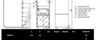
Boilers G-150, G-420, G-950 are designed for cooling process gases in order to condense sulfur vapor and produce saturated steam in the process of neutralizing hydrogen sulfide gases. Boilers G-250, G-345, G-250P, G-345P, G550P, G-145B, G-1030B, G-330BI, G-445BI, G-660BI are designed to generate saturated steam by using process and waste heat gases in chemical, petrochemical, metallurgical and other industries. Vertical boilers V-90B and G-460B are designed for cooling converted gases and producing saturated steam. Boilers G-400PE and G-420BPE are designed to produce superheated steam by using the heat of exhaust gases from a gas turbine and the heat of nitrous gases in the scheme for producing weak nitric acid. Energy-technological boilers KS-200 VTKU-M and KS-450 VTKU-M are installed behind sulfur pyrite roasting furnaces in a fluidized bed with a capacity of 200 and 450 t/day. Previously, UKKS (water tube) and GTKU (gas tube) boilers were produced for these purposes. Waste heat boilers of the KU series are designed to produce superheated steam based on the use of sensible heat from gases coming out of open-hearth, heating and other technological furnaces. The central steam superheater TsP-60-S is designed to superheat saturated steam produced by waste heat boilers. Blast-furnace gas with a calorific value of at least 1000 kcal/m3 is used as fuel. The energy-technological boiler SETA-Ts-100-2M is intended for installation in the technological line for the production of sulfuric acid. Sulfur combustion is carried out in a cyclone pre-furnace with an excess air coefficient α=2. The energy-technological boiler PKS-Ts-10/40 is designed for burning hydrogen sulfide and cooling combustion products. Recovery boilers KSTK-35/40-100 and KST-80 are designed to cool gases entering them from the dry coke quenching chamber and produce superheated steam. Converter gas coolers (OCG) are designed for afterburning and cooling of gases leaving steel converters. The characteristics of some types of waste heat boilers are given in Table. 1, 2, 3, 4. The main elements of a waste heat boiler are a drum, an evaporative heating surface, a steam superheater and a water economizer. In some cases, there may be no superheater or water economizer, or both. The principal design diagram of the waste heat boiler is shown in Fig. 2.1. When the initial gas temperature is below 800°C, the superheater, as a rule, is located first along the gas flow. The procedure for thermal calculation of a waste heat boiler given below specifically considers this case, which is most often encountered in practice. For real operating conditions, it is necessary to be able to evaluate the performance of existing equipment at various flow rates and parameters of exhaust gases. The purpose of the calculation is to determine the amount of heat absorbed by the existing heating surfaces and the steam production of the waste heat boiler at given parameters.
Table 2.1 Main technical characteristics of waste heat boilers
| Boiler type | Purpose | Steam production, t/h | Pressure, MPa | Temperature, С0 | Flue gas volume, m3/h | Gas temperature in front of the boiler, Co | Flue gas temperature Co |
| 1 | 2 | 3 | 4 | 5 | 6 | 7 | 8 |
| G-150 | Cooling of process gases in the process of neutralizing hydrogen sulfide gases | 0,53 | 0,5 | 151 | 2293 | 360 | 159 |
| G-420 | 1,0 | 0,5 | 151 | 7257 | 280 | 155 | |
| G-950 | 5,0 | 0,5 | 151 | 21870 | 287 | 161 | |
| G-250 | Cooling of process gases | 3,2 | 1,4 | 194 | 16000 | 600 | 270 |
| G-345 | 8,1 | 1,4 | 194 | 40000 | 600 | 260 | |
| G-250P | 3,1 | 1,4 | 240 | 16000 | 600 | 260 | |
| G-345P | 7,9 | 1,4 | 260 | 40000 | 600 | 250 | |
| G-550P | 11,6 | 1,4 | 280 | 55000 | 600 | 240 | |
| G-145B | 4,7 | 1,4 | 194 | 8000 | 1200 | 280 | |
| G-1030B | 31 | 1,4 | 194 | 50000 | 1200 | 240 |
End of table 2.1
| 1 | 2 | 3 | 4 | 5 | 6 | 7 | 8 | |
| G-330BI | 9,5 | 1,4 | 194 | 15000 | 1200 | 310 | ||
| G-445BI | 15,7 | 1,4 | 194 | 25000 | 1200 | 250 | ||
| G-660BI | 23,3 | 1,4 | 194 | 35000 | 1200 | 235 | ||
| V-90B | 5,0 | 0,8 | 170 | 25000 | 850 | 560 | ||
| V-460B | 6,6 | 1,4 | 194 | 60000 | 400 | 225 | ||
| G-400PE | In the production of nitric acid | 7,5 | 1,6 | 230 | 66500 | 405 | 185 | |
| G-420BPE | 25 | 15 | 250 | 56200 | 900 | — | ||
| KS-200 VTKU-m | Behind the fluidized bed kilns | 11 | 4 | 440 | 20000 | 900 | 450 | |
| KS-450 VTKU-M | 25 | 4 | 440 | 44000 | 900 | 450 | ||
| UKKS 8/40 | 8 | 4,0 | 450 | 20740 | 825 | 350 | ||
| UKKS 4/40 | 4 | 4,4 | 255 | 10370 | 900 | 350 | ||
| KS-100 GTKU | 7,1 | 4,3 | 255 | 10370 | 900 | 350 | ||
| KS-200 GTKU | 11 | 4,0 | 450 | 20740 | 900 | 430 | ||
| KU-40-1 | Use of heat from waste gases at ferrous metallurgy enterprises | 12,9 | 4,5 | 385 | 40000 | 850 | 248 | |
| KU-40-1 | 13,45 | 1,8 | 385 | 40000 | 850 | 227 | ||
| KU-60-2 | 19 | 4,5 | 392 | 60000 | 850 | 252 | ||
| KU-60-2 | 19,9 | 1,8 | 366 | 60000 | 850 | 229 | ||
| KU-80-3 | 25,8 | 4,5 | 385 | 80000 | 850 | 248 | ||
| KU-80-3 | 26,9 | 1,8 | 358 | 80000 | 850 | 227 | ||
| KU-100-1 | 32,6 | 4,5 | 382 | 100000 | 850 | 242 | ||
| KU-100-1 | 33,9 | 1,8 | 360 | 100000 | 850 | 242 | ||
| KU-125 | 40,8 | 4,5 | 385 | 125000 | 850 | — | ||
| KU-125 | 42,4 | 1,8 | 365 | 125000 | 850 | — | ||
| KU-100-B | 32,5 | 1,8 | 395 | 100000 | 850 | 232 | ||
| KU-150 | 50,5 | 4,5 | 393 | 150000 | 850 | 213 | ||
| KSTK-35/40-100 | Waste heat boiler installation | 32,4 | 4 | 440 | 100000 | 800 | 170 | |
| KST-80 | 20 | 3,9 | 440 | 73944 | 800 | 180 | ||
Table 2.2 Main technical characteristics of waste heat boilers with fuel combustion
| Boiler type | Purpose | Steam production, t/h | Pressure, MPa | Temperature, C | Type of fuel | Fuel consumption | Flue gas temperature C |
| SETA-C-100-2M | Energy technology unit | 13,1 | 4 | 440 | Sulfur | 100 t/day | 490 |
| PKSTS-10/40 | 9,5 | 4 | 354 | Hydrogen sulfide | 1600 m3/h | 589 | |
| TsP-60-S | Central superheater | 40 | 1,9 | 216-380 | Blast gas | 4605 m3/h | 204 |
Table 2.3 Main structural dimensions of elements of gas-tube waste heat boilers
| Boiler size | Smoke pipes | ||||
| Diameter and thickness, D xd, mm | Quantity n, pcs | Total external cross-section ∑fif m2 | Total internal cross-section ∑fof m2 | Length, mm | |
| 1 | 2 | 3 | 4 | 5 | 6 |
| G-150 | 32x3 | 356 | 0,286 | 0,08 | 4960 |
| G-420 | 32x3 | 1044 | 0,839 | 0,236 | 4960 |
| G-420 | 32x3 | 1600 | 1,286 | 0,362 | 8100 |
| G-950 | 50x3 | 500 | 0,981 | 0,76 | 3610 |
| G-345, G-345P | 50x3 | 500 | 0,981 | 0,76 | 4960 |
| G-550P | 50x3 | 700 | 1,373 | 1,064 | 4960 |
| G-145B | 50x3 | 212 | 6,416 | 0,322 | 4960 |
End of table 2.3
| 1 | 2 | 3 | 4 | 5 | 6 |
| G-1030B | 50x3 | 1032 | 2,025 | 1,569 | 7300 |
| G-330BI | 50x3 | 648 | 1,271 | 0,985 | 3400 |
| G-445BI | 50x3 | 648 | 1,271 | 0,985 | 4960 |
| G-660BI | 50x3 | 648 | 1,271 | 0,985 | 7300 |
| V-90B | 80x3.5 | 99 | 0,497 | 0,414 | — |
| V-460B | 50x3 | 648 | 1,271 | 0,985 | 4960 |
| G-400PE | 50x3 | 790 | 1,550 | 1,208 | 3610 |
| G-420BPE | 50x3 | 480 | 0,942 | 0,729 | 6300 |
Table 2.4 Calculation and design characteristics of convective, coil unified HRSGs
| Characteristic | Boiler size | Evaporative packages, m2 | Superheater | Economizer | |||||
| 1st | 2nd | 3rd | 4th | ||||||
| Estimated heating surface area, F, m2 | KU-40-1 | 30 | 109,5 | 122 | 110,5 | 43,5 | 185 | ||
| KU-60-1 | 46 | 173 | 92 | 175 | 70 | 247 | |||
| KU-80-3 | 60 | 219 | 244 | 221 | 87 | 370 | |||
| KU-100-1 | 85 | 285 | 315 | 295 | 110 | 460 | |||
| KU-125 | 110 | 370 | 410 | 380 | 144 | 615 | |||
| KU-150 | 133,2 | 415 | 475 | 436 | 166 | 725,1 | |||
| Number of parallel connected coils, z | KU40-1 | 18 | 38 | 38 | — | 19 | 12 | ||
| KU-60-2 | 28 | 60 | 60 | — | 30; 60 | 16 | |||
| KU-80-3 | 36 | 76 | 76 | — | 38; 76 | 24 | |||
| KU-100-1 | 40 | 80 | 80 | — | 40; 80 | 24 | |||
| KU-125 | 52 | 104 | 104 | — | 52; 104 | 32 | |||
| KU-150 | 64 | 120 | 120 | — | 60 | 32 | |||
| Clear cross-sectional area for the passage of combustion products, Fp.s. m2 | KU40-1 | 4,315 | 3,17 | 3,17 | 2,885 | 3,17 | 3,18 | ||
| KU-60-2 | 7,0 | 5,06 | 5,06 | 4,63 | 5,066 | 4,55 | |||
| KU-80-3 | 8,63 | 6,34 | 6,34 | 5,77 | 6,34 | 6,36 | |||
| KU-100-1 | 10,8 | 8,04 | 8,04 | 7,35 | 8,04 | 7,67 | |||
| KU-125 | 13,2 | 10,3 | 10,3 | 9,4 | 10,3 | 9,8 | |||
| KU-150 | 16,6 | 12,5 | 12,5 | 11,5 | 12,5 | 9,65 | |||
End of table 2.4
| Characteristic | Boiler size | Evaporative packages, m2 | Superheater | Economizer | |||
| 1st | 2nd | 3rd | 4th | ||||
| Free cross-sectional area for steam and water, f, m2 | KU-40-1 | 0,0096 | 0,0202 | 0,0202 | — | 0,0101 | 0,0063 |
| KU-60-1 | 0,0148 | 0,0318 | 0,0318 | — | 00159 00318 | 0,0085 | |
| KU-80-1 | 0,0192 | 0,0404 | 0,0404 | — | 0,0202 0,0404 | 0,0170 | |
| KU-100-1 | 0,0212 | 0,0425 | 0,0425 | — | 0,0212 0,0425 | 0,0170 | |
| KU-125 | 0,0276 | 0,0552 | 0,0552 | — | 0,0276 0,0552 | 0,0170 | |
| KU-150 | 0,0340 | 0,0636 | 0,0636 | — | 0,0318 | 0,0170 | |
| Pipe diameter | 32/26 | ||||||
| Number of rows along the gas flow | For all boilers | 12 | 20 | 22 | 8 | 3; 16 | |
| Steps in width | 172 | 86 | 90 | — | |||
| Steps in depth | 70 | — | — | ||||
| Effective thickness of the radiating layer, m | 0,161 | — | |||||
Table 2.5 Composition of gases from various technological processes
units
| Boiler type | Gas composition, % | ||||||
| CO2 | N2 | SO2 | CO2 | O2 | H2 | H2O | |
| Combustion products of medium composition | 13 | 78,5 | — | — | 1,5 | — | 7 |
| Boilers behind sulfur pyrite kilns | — | 78,5 | 5,5 | — | 10 | — | 6 |
| Boilers for cooling converted gases in ammonia production | 16,8 | 14,0 | — | 3,4 | — | 41,8 | 24 |
| Boilers for dry coke quenching plants | 5 | 66,6 | 0,04 | 18 | — | 10 | — |
Table 2.6 Heat capacity of gases
| t, 0C | Composition of flue gases | ||||||
| O2 | N2 | CO | CO2 | H2O | CO2 | H2 | |
| 1 | 2 | 3 | 4 | 5 | 6 | 7 | 8 |
| 0 | 1,3046 | 1,2992 | 129922 | 1,5914 | 1,4943 | 1,7333 | 1,278 |
| 100 | 1,3167 | 1,304 | 1,3013 | 1,8132 | 1,5056 | 1,813 | 1,2905 |
| 200 | 1,3356 | 1,3042 | 1,3075 | 1,7961 | 1,5219 | 1,888 | 1,299 |
| 300 | 1,3565 | 1,3113 | 1,3172 | 1,8711 | 1,5424 | 1,957 | 1,3 |
| 400 | 1,3766 | 1,3205 | 1,3289 | 1,9377 | 1,5654 | 2,018 | 1,303 |
| 500 | 1,3967 | 1,3327 | 1,3431 | 1,9967 | 1,5893 | 2,072 | 1,307 |
| 600 | 1,416 | 1,3456 | 1,3578 | 2,0494 | 1,6144 | 2,1114 | 1,309 |
| 700 | 1,4344 | 1,359 | 1,3716 | 2,0967 | 1,6412 | 2,152 | 1,311 |
| 800 | 1,4503 | 1,3720 | 1,3854 | 2,1395 | 1,6684 | 2,186 | 1,316 |
| 900 | 1,4645 | 1,385 | 1,3984 | 21788 | 1,6957 | 2,215 | 1,324 |
| 1000 | 1,4775 | 1,3971 | 1,4114 | 2,214 | 1,7229 | 2,24 | 1,328 |
Boilers using waste gases from technological units (mainly industrial furnaces) are called HRSG boilers.
The most widespread are the unified general purpose boilers of the Belgorod Power Engineering Plant: KU-40-1, KU-60-2, KU-80-3, KU-125, KU-150. They are intended for installation behind open-hearth furnaces, heating furnaces and other technological units. In the designation of the KU type, the first two- or three-digit number indicates the calculated passage of combustion products for it in thousand m3/h for 0°C, and the second single-digit number indicates the serial number of the modification.
The boilers are made from standardized coil sections, have multiple forced circulation and a U-shaped arrangement of gas ducts. The boilers have high aerodynamic resistance (about 1.2 kPa/m2), and when operating on exhaust gases with mechanical impurities, they quickly become clogged. The gas density of the HRSG is low and air leakage into the gases is significant. HRSGs behind open-hearth furnaces are installed for each furnace, and when utilizing gas from heating furnaces, it is possible to install one boiler for several units.
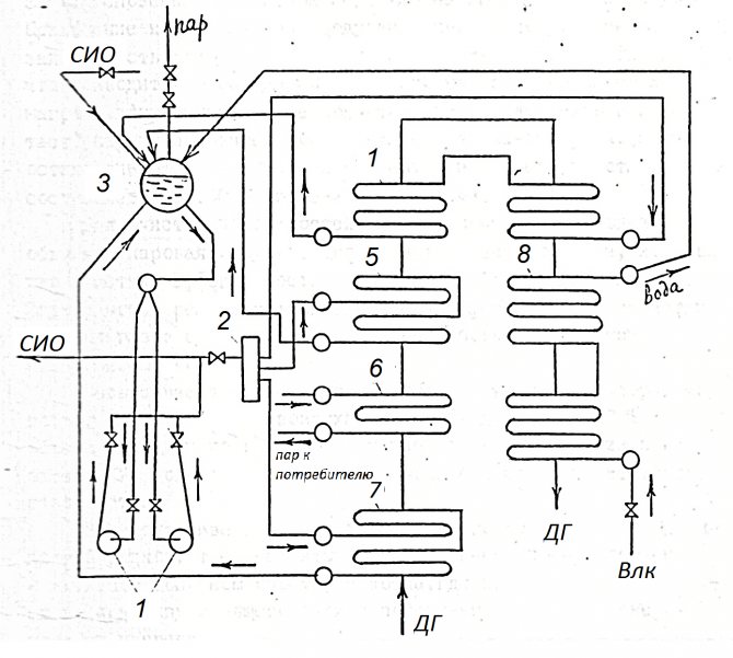
The frequently used boiler KU-100 (Fig. 2.1) is characterized as follows. Three sections of the evaporation part /positions 4,5,7/ along the flue gases /DG/ are connected in series, and along the water supplied by circulation pumps 1 - in parallel. The evaporation is single-stage, the superheat of the steam is not regulated. Due to the selection of the lengths of the coils of each section, their hydraulic resistance is the same, and its value in parallel connection is several times less than it would be in series connection. From drum 3, water flows into slag catcher 2, and then into the evaporation sections. From there, the water, becoming a steam emulsion, enters the drum, where feedwater Vpi is also sent through the economizer 8 in exchange for the steam leaving through the superheater 6 to consumers. The boiler design provides for the possibility of integrated work with the evaporative cooling system of the furnaces.
The complication of the operation of the heat exchanger due to the clogging of heat exchange surfaces by entrainment occurs at enterprises in various industries. In particular, this happens in the HRSG behind open-hearth furnaces during the transition to oxygen smelting. The use of oxygen for purging the bath sharply increases the dust content of the exhaust gases in front of the boiler /up to 10..15 g/m3/, which leads to the formation of deposits on its heating surfaces. The aerodynamic resistance of the boiler increases sharply, and steam production decreases by two to three times. The boiler is stopped for cleaning. the duration of its operation is 40...60% of the furnace operating time.
To clean heating surfaces, water washing, steam blowing, shot cleaning, vibration cleaning, and pulse cleaning are used. The effectiveness of all these methods is insufficient. The problem can be solved by the device of highly efficient pre-treatment of flue gases using a dry method or the development of non-clogging boiler designs.
The degree of compaction of the boiler enclosing structures is very important, since air leakage through them reaches 40% of the volume of suitable gas, which reduces the thermal performance of the boiler, increases the power consumption of traction devices and gas purification.
In the future, boilers with a volumetrically cooled firebox are attracting attention, i.e. developed radiation surfaces in the active combustion volume, and boilers where the process is carried out according to the principle of a fluidized bed with heating surfaces immersed in it.
Figure 2.1 Scheme of waste heat boiler KU-100-1
Table 2.7 Characteristics of waste heat boilers for open-hearth furnaces
| Parameter | KU-60-2 | KU-80-3 | KU-100-1 |
| Amount of flue gases in front of the boiler, thousand m3/h | 60 | 80 | 100 |
| Estimated gas temperature in front of the boiler, °C | 600 | 650 | 650 |
| Design flue gas temperature, °C | 210 | 210 | 210 |
| Working steam pressure, kPa | |||
| Steam temperature /at pressure 1800/4500 kPa/, °C | |||
| Estimated steam capacity, kg/s | 3,67 | 4,94 | 6,22 |
| Heating surface, m2: Total………………… Superheater…………………. Evaporation surface………. Water economizer……………. Pre-included package…………… | 903 70 540 247 46 | 1201 87 684 370 60 | 1550 110 895 460 85 |
| Drum inner diameter, mm | 1508 | 1508 | 1508 |
| Live cross-section of the passage for steam /water/, m2: Superheater………………… Evaporating sections: I……………………………………………………… II…………………………… ………… III…………………………………… IV…………………………………….. Economizer………………………… | 0,0148 0,0318 0,0318 — 0,0085 | 0,0192 0,0404 0,0404 0,0404 0,0127 | 0,0212 0,0425 0,0425 0,0425 0,0127 |
| Live cross-section of the passage for flue gases, m2: Superheater………………… Evaporating sections: I……………………………………. II……………………………………. III……………………………………………………… IV…………………………………… Economizer………………………. | 5,06 7,0 5,06 4,63 — 4,55 | 6,34 8,63 6,34 6,34 5,77 6,36 | 8,04 10,8 8,04 7,35 7,35 7,67 |
End of table 2.7
| Parameter | KU-60-2 | KU-80-3 | KU-100-1 |
| Number of rows of pipes along the flow path: Superheater………………….. Evaporating sections I………………………………………………………. II……………………………………. III……………………………………………………… IV…………………………………… Economizer………………………… | 8 12 22 20 — 2x20 | 8 12 20 22 22 2x20 | 8 12 22 22 22 2x20 |
| Pipe spacing along the bundle width, S1, mm: Evaporation sections……………… Others…………………………… | 172 86 | 172 86 | 172 86 |
| Pipe spacing along the bundle depth, S2, mm | 70 | 70 | 70 |
Notes: numerator – for operating steam pressure 1800 kPa; denominator – for 4500 kPa.
Features of work
During operation of the boiler unit, its heat exchanger is covered with substances contained in the flue gases. This does not have the best effect on the efficiency of the recycler. To make the efficiency as high as possible, you can install a thermal oxidizer of volatile organics in front of it.
If the need to use the heat of exhaust gases arises only from time to time, the flow of emissions to the boiler can be regulated. For this, a special bypass is used - a block that redirects waste into the chimney. The bypass function can be controlled via a dry contact, which has an open and blocked state, or using an external analog signal. In the latter case, the process is tied to regulating the opening angle of the damper.