The balancing valve allows you to maintain equal rates of flow and flow of the working fluid in the pipes. The products help maintain optimal temperature and circular pressure parameters, prevent accidents and deformations in pipelines due to temperature changes and excess volumes of fluids passed through.
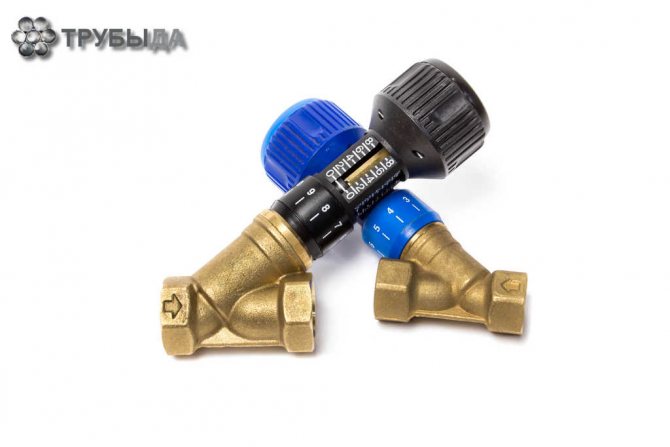
Manual balancing valve
Need for use
Heating systems require balancing, which is a hydraulic adjustment. The purpose of these manipulations is to bring the water flow through individual branches of the circuit to the required value, only in this way will the required amount of heat be supplied to each radiator. If we are talking about simple systems, the required coolant flow is ensured using correctly selected pipe diameters.
Watch a video about the balancing valve in action
Usually the valve is installed with additional devices that increase the efficiency of heating the room:
- input automation device;
— thermostats for radiators.
During the operation of the heating system, prerequisites arise that indicate the need for modernization:
— in case of changes in the pipeline design;
— when replacing radiators with other parameters;
— in case of poor-quality installation of the circuit;
— when an error is identified in design calculations.
Use in complex systems
Complex systems require adjustment in their operation using special washers, the size of the passage of which ensures the flow of water in the required volume. The listed methods are outdated; today a modern method is used, which is expressed in the installation of balancing valves. These devices are manual valves that are used to regulate the flow of coolant. The mechanism has an addition that blocks the flow; fittings are used for this.
Balancing valve for a heating system: its purpose, installation, equipment configuration
It often happens that the coolant distributes heat between rooms poorly. Where there is a lack of it, the air does not warm up, and where there is an excess, it is too stuffy. To return everything to normal, the system must be balanced using hydraulic adjustment.
Uniform distribution of heat throughout the building is one of the factors influencing the continuous high-quality operation of the system.
Many people believe that room balancing is only necessary in multi-story buildings. This is far from true.
Heat is distributed incorrectly even in small buildings. Temperature regulators do not always help (read: what they are and why they are needed). Therefore, the only solution is to install a balancing valve.
https://www.youtube.com/watch?v=E-7piNgaW0w
This happens because the coolant moves along the path of least resistance. First, it fills the space near the heating system. Distant areas do not heat up because the liquid has cooled in previous stages. This is fraught with excessive energy consumption.
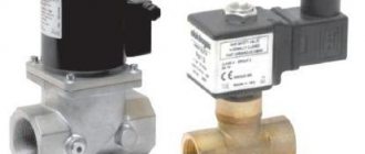
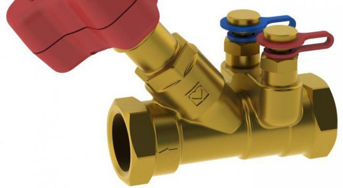
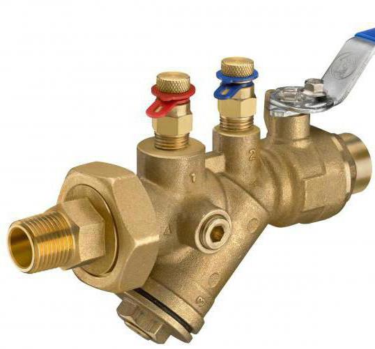
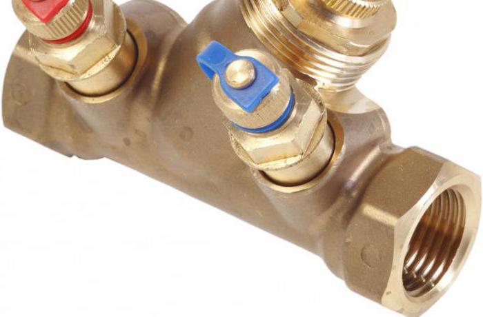
This is what a manual valve looks like
A manual balancing valve for a heating system solves this problem. With its help, the liquid is distributed evenly in the pipeline. As a result, excess pressure drops in the risers are eliminated, and the system returns to normal.
There are two types of devices:
- Manual (read more here) - used to configure individual sections and the system as a whole. They measure pressure at control points and are able to turn off some elements.
- Automatic - installed in pairs on the input and return circuits. They do not require constant reconfiguration, if they were configured correctly in the first installation.
Installation and adjustment of balancing valves
The valve is installed in accordance with the instructions.
It is important to consider some recommendations:
- The valve is installed on the supply pipe, where you first need to install a strainer (read more about the installation location here).
- Nanometers are installed on both sides of the device.
- Unless the instructions indicate otherwise, the structure can be installed in any position.
- The arrow must coincide with the fluid flow in the pipeline.
- The valve body should not experience additional loads: tension, compression or torsion.
- The installation location must be easily accessible.
- It is necessary to maintain straight sections before and after installing the valve: from 2 to 10 device diameters.
Principle of operation
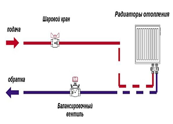
Once you have learned what the balancing valve is used for, the principle of operation of which will be described below, you can begin installing the device. First you need to understand the principle of balancing the heating system. To do this, you can imagine a dead-end branch that has several radiators, the latter acting as energy consumers. A certain volume of coolant, heated to the design temperature, is supplied to them through the pipes. It is determined depending on how much thermal energy will be needed to heat the premises.
A manual balancing valve is used when radiators do not have a thermostatic valve and the water flow for each of them is constant. The mentioned device should be located on the return pipeline, in a place where it can be inserted into the common line. This allows you to carry out the necessary measurements by setting the valve to the required number of revolutions. A certain constant flow of water in the regulated branch will be guaranteed. However, users quite often encounter that the flow rate changes; this can happen when thermostatic regulators are installed on radiators. They are designed to control the intensity of heating of the room and create an obstacle in the way of water, reducing the volume of its flow. In this case, the flow rate of the coolant volume in the return common pipeline will change.
Kinds
Valves with balancing functions are divided into models:
- automatic (dynamic);
- manual type (static).
Automatic products allow you to maintain the required pressure drop in two-pipe risers or single-pipe heating and water supply systems. The element helps to block the flow, drain liquid through the drainage insert, and change the flow rate.
Supplemented with a drive (electric or geared), an automatic device can be used to regulate heat exchange devices in ventilation and air conditioning systems of buildings. The variety of valves is optimal for spaces with a large number of batteries; the products help create separate heat exchange areas in systems. The adjustment device is driven by a capillary tube.
The manual balancing valve is a valve-type device and functions as a diaphragm. The products are optimal for pipelines in which stable pressure levels are maintained. The devices are installed in private residential cottages and apartment buildings with a limited number of radiators. The product is optimal for buildings with no more than 5 batteries.
The type of valve not only ensures hydraulic balance, but also allows individual parts of the system to be switched off. The manual type of the valve allows repair work to be carried out without turning off the entire heating system. Special instruments help measure pressure fluctuations and control settings.
Devices are also classified according to:
- type of operating environment (water, steam, glycol solution, etc.);
- functional characteristics (pressure level, temperature, volume of fluids passed through);
- type of buildings (industrial, public, private residential or multi-apartment);
- location (reserve section, supply or return pipeline);
- type of connection to the pipeline (flange or threaded).
Based on the type of work tasks, valves are divided into devices responsible for maintaining:
- stable temperature;
- pressure indicators;
- volumes of transported trains.
Devices are made from different materials:
- brass alloys (suitable for threaded and flanged connections);
- cast iron (used only for flanged valves);
- carbon steel (universal, resistant to corrosion processes, deformation, etc.).
For reference
A manual balancing valve will guarantee a certain volume of coolant, which will allow you to achieve the desired effect when the number of batteries is small and does not reach 5 pieces. If you limit the control limits of thermostats, then the existing circuit can be easily customized. If the number of radiators is more than mentioned, then they will go to waste. The thermostat installed on the first battery will block the flow of coolant, which will cause an increase in flow on the second radiator. The valve on it will close, the flow will move to the third radiator, and so on. Ultimately, such work will lead to the fact that some batteries will overheat unnecessarily, while others will remain cold, and the branch will become unbalanced. An automatic balancing valve must be installed on a riser or branch with a sufficiently large number of heating devices, only then the system will work smoothly.
Valves for the heating system: purpose and application
Valves are integral elements of any heating system (HC), regardless of the chosen circuit and configuration of the circuits. With the help of these simple devices, heat supply parameters are adjusted, ensuring the safety and stability of the system. This publication will discuss the main valves used in centralized and autonomous heating systems, their purpose, operating principle and design features.
Criterias of choice
The number and parameters of valves required for a specific CO are selected at the calculation and design stage. The main criteria that influence the selection of these elements are:
- Type, circuit and configuration of CO.
- Temperature conditions (nominal and maximum).
- System pressure (working and maximum).
- Pipeline cross-section and thread type.
- Type of coolant (water, brines, antifreeze).
The operation of these devices stabilizes CO, making it effective and safe. Anyone who is independently installing a heating system in their home needs to know its purpose and operating principle. All valves can be divided according to their purpose into three categories: safety, control and regulation groups.
Everyone knows that any CO is an increased source of danger, since the coolant in the system is under pressure. And the higher the temperature, the higher the pressure (in closed CO). Next, let's look at the devices that are responsible for the safety of CO operation.
Safety
In most models of modern boiler units, manufacturers provide a safety system, the “key figure” of which is a safety valve included directly in the boiler heat exchanger or in its piping.
The purpose of a safety valve in a heating system is to prevent pressure in the system from increasing above the permissible limit, which can lead to: destruction of pipes and their connections; leaks; explosion of boiler equipment
The design of this type of fittings is simple and unpretentious. The device consists of a brass body containing a spring-loaded locking diaphragm connected to a stem. The elasticity of the spring is the main factor that keeps the membrane in the locked position. The adjustment handle adjusts the spring compression force.
When the pressure on the membrane is higher than the set one, the spring is compressed, it opens and the pressure is released through the side hole. When the pressure in the system cannot overcome the elasticity of the spring, the membrane will return to its original position.
Tip: Buy a safety device with pressure adjustment from 1.5 to 3.5 Bar. Most models of solid fuel boiler equipment fall into this range.
Air vent
Quite often, air pockets form in the CO. As a rule, there are several reasons for their appearance:
- boiling of the coolant;
- high air content in the coolant, automatically added directly from the water supply;
- As a result of air leaks through leaky connections.
The result of air locks is uneven heating of radiators and oxidation of the internal surfaces of the metal elements of the CO. The heating system air vent valve is designed to remove air from the system automatically.
Structurally, the air vent is a hollow cylinder made of non-ferrous metal, in which there is a float connected by a lever to a needle valve, which in the open position connects the vent chamber to the atmosphere.
In operating condition, the internal chamber of the device is filled with coolant, the float is raised, and the needle valve is closed. When air enters and rises to the upper point of the device, the coolant cannot rise in the chamber to the nominal level, and therefore the float is lowered and the device operates in exhaust mode. After the air escapes, the coolant rises in the chamber of this type of fitting to the nominal level, and the float takes its normal place.
Back
In gravity-flow CO, there are conditions under which the coolant can change direction of movement. This threatens to damage the heat exchanger of the heat generator due to its overheating. The same can happen in fairly complex systems with forced movement of the coolant, when water flows back into the boiler through the bypass pipe of the pumping unit. The mechanism of operation of a check valve in a heating system is quite simple: it allows the coolant to flow only in one direction, blocking it when moving back.
There are several types of this type of fittings, which are classified according to the design of the locking device:
- disc-shaped;
- ball;
- petal;
- bivalve.
As is already clear from the name, in the first type, a steel spring-loaded disk (plate) connected to a rod acts as a locking device. In a ball valve, a plastic ball acts as a shutter. Moving in the “right” direction, the coolant pushes the ball through a channel in the housing or under the cover of the device. As soon as the circulation of water stops or the direction of its movement changes, the ball, under the influence of gravity, takes its original position and blocks the movement of the coolant.
In the petal type, the locking device is a spring-loaded lid, which lowers when the direction of water in the CO changes under the influence of natural gravity. The double-leaf element is installed (usually) on large diameter pipes. The principle of their operation is no different from the petal one. Structurally, in such fittings, instead of one petal spring-loaded from above, two spring-loaded flaps are installed.
These devices are designed to regulate temperature, pressure, and also stabilize the operation of CO.
Balancing
Any CO requires hydraulic adjustment, in other words, balancing. It is carried out in various ways: with correctly selected pipe diameters, washers, with different flow areas, etc. The most effective and at the same time simple element in setting up the operation of CO is considered to be a balancing valve for the heating system .
The purpose of this device is to supply each branch, circuit and radiator with the required volume of coolant and amount of heat.
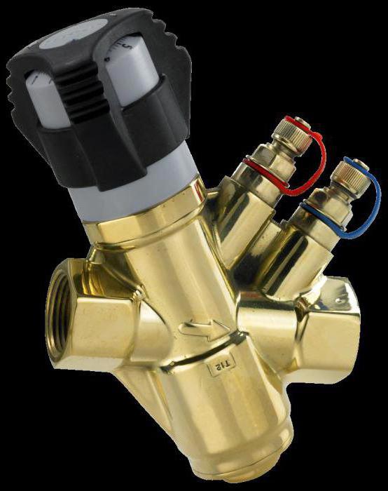
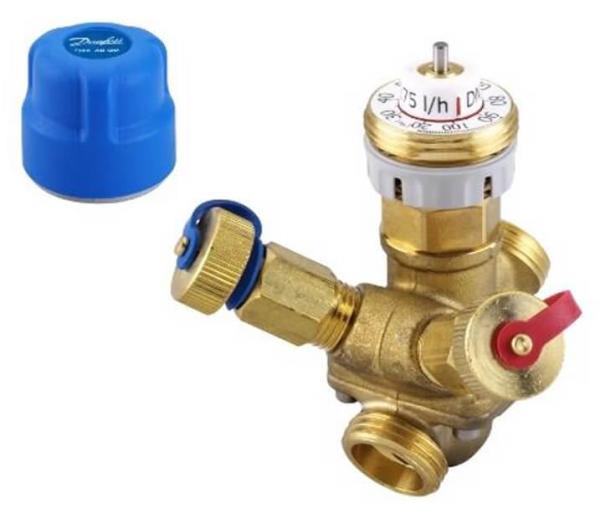
The valve is a regular valve, but with two fittings installed in its brass body, which make it possible to connect measuring equipment (pressure gauges) or a capillary tube as part of an automatic pressure regulator.
The operating principle of a balancing valve for a heating system is as follows: By turning the adjusting handle, it is necessary to achieve a strictly defined coolant flow rate.
This is done by measuring the pressure at each fitting, after which the number of turns of the adjustment handle to achieve the required water flow for each CO circuit is determined using a diagram (usually supplied by the manufacturer to the device).
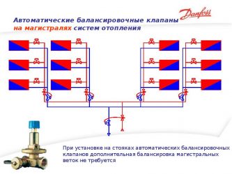
For circuits with up to 5 radiators, manual balancing regulators are installed. On branches with a large number of heating devices - automatic.
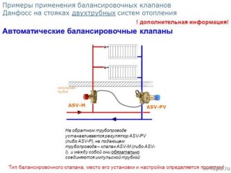
Operating principle of a valve on a riser with a large number of radiators
If an automatic balancing valve is used under the conditions described above, then the operating principle is somewhat different. The valve is adjusted to the maximum design water flow. During operation, when the thermostat of any battery reduces hot water consumption, the pressure in the area will begin to increase. The automatic regulator will receive an impulse through a capillary tube, this will allow the device to quickly respond by adjusting the water flow, then the remaining thermostats will not have time to operate, the flow will not be blocked, and the system will remain hydraulically balanced.
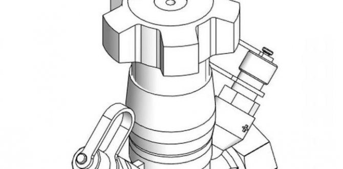
What is a balancing valve: its principle of operation
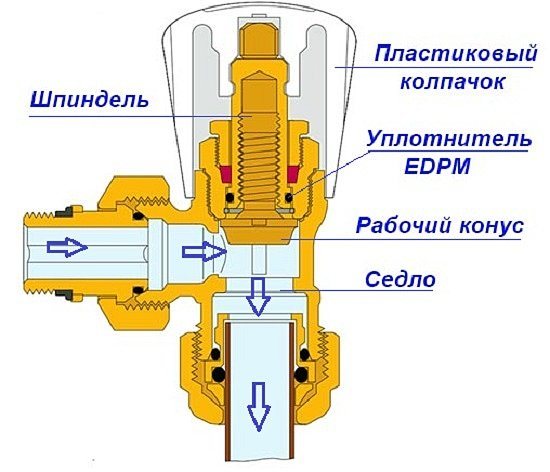
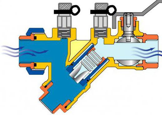
A balancing valve is a simple mechanical device that is part of a pipeline structure. In appearance it resembles a ball valve. The valve is made of bronze, brass or cast iron. It has a metal body with a latch inside. The spool is driven by an inclined rod.
The operating principle of the valve is based on full automatic level control or manual rotation of the shutter handle. When the handle is turned, the spindle rotates the spool located inside the valve, which changes its position, as well as the cross-section of the pipes.
Classification
The balancing valve, the operating principle of which was described above, is offered for sale in a wide range. Before you make a purchase, you must understand the classification. Thus, when choosing, it is necessary to take into account the design parameters of the system at the installation point. The technician must pay attention to the maximum pressure of the working medium and the nominal parameter, and also take into account the pressure difference in the return and supply circuits.
The valve may belong to one or another class depending on the area of use. Thus, the devices are used at individual construction sites, housing and communal services, in industrial facilities and at sections of main pipelines. The balancing valve, the operating principle of which you should know before purchasing the device, can be selected according to the type of piping system, which is designed for air conditioning, hot or cold water supply, cooling or heating. Among other things, the devices described differ in the type of coolant, such as steam, water or glycol solution. According to the type of installation, valves are divided into fixed and adjustable.
Areas of application
The key task is to create the proper hydraulic regime in the pipeline circuit at the established level. There is a certain difference in the operation of manual and automatic modification, so using two different types within the same network is not recommended if possible. It is better to use them in separate sections of a branched pipeline or in autonomous complexes, where they can perform a useful function in regulating pressure without regard to the likely incompatibility of different models of units. Thanks to the use of balancing valves, the heating system will be protected from excessive pressure in areas where low-strength components are used.
The scope of application is divided according to the following criteria:
- reasonable cost (compared to units of similar purpose);
- clear controls that simplify operation;
- support for adjustment without shutting off the supply (changing the coolant throughput from the boiler);
- ease of repair and maintenance (no special knowledge or tools required).
The shortcomings of the equipment are so minor that it is difficult to find negative comments or articles about Ballomax balancing valves. When purchasing, a unit is selected that fits a pipe with a certain diameter. It is even better to order installation from competent specialists. The wear resistance of such products is high, which reduces the number of breakdowns and reduces maintenance costs.
Main types of valves
If you are interested in the MSV balancing valve, then it is offered for sale in a wide variety; among other models, you can see devices with manual adjustment, with the help of which it is easy to adjust individual sections of the system and the entire pipeline, determining the pressure and flow of the medium at control points. Using manual balancing valves, you can turn off individual areas, freeing them from the working coolant. The main advantage is low cost, but you should pay attention to some disadvantages. Among the main ones is the ability to set the balance only for the average calculated parameters of direct current. When flow fluctuates, as occurs in plumbing systems, the balancing can be disrupted.
An automatic balancing valve, the price of which is 6,000 rubles, can be automatic; it is installed on the return and inlet circuits. Another type of valve provides the ability to regulate the temperature of the working environment.
Balancing valve selection
To choose the right valve for your heating system, you must consider:
- type of equipment;
- technical specifications;
- installation method;
- manufacturing company.
Varieties
Depending on the control method, there are:
- manual;
- automatic.
The manual setting is done by the user independently by rotating the handle that opens/closes the flow of coolant.
With manual control method
The manual valve is different:
- stable operation at constant pressure in the heating system;
- ease of control;
- low cost.
The manual balancing valve is preferably installed in systems with a small number of connected radiators and where there is sufficient free space for control.
Equipment operating in automatic mode allows you to achieve uniform adjustment of the system.
An automatic valve, in contrast to manually controlled equipment, helps to simultaneously control several heating radiators connected to the same line.
With autonomous control method
The advantages of equipment operating in automatic mode are the following aspects:
- quick response to changes in heating system parameters;
- the ability to maintain constant pressure, which eliminates the possibility of hydraulic shocks leading to leaks;
- the ability to create zones with special conditions, for example, for growing seedlings.
Among the negative factors are:
- high cost;
- the need to install additional equipment in heating systems - thermostats.
You can also classify balancing valves:
- according to the engineering system. There are combined and specific. Specific valves can be used in pipelines for any purpose (heating, water supply, etc.) only if the appropriate model is selected. Combined ones are universal;
- according to the type of locking device. Valves and ball mechanisms are manufactured. The shut-off and balancing valve allows for more precise adjustment of the system, unlike a ball valve. However, when using a coolant in the form of a thick liquid, it is advisable to use ball mechanisms.
Determination of technical parameters
At the next stage, the device is selected according to technical parameters. Of significant importance are:
- Maximum temperature;
- operating and peak pressure in the system;
- through hole (Dn);
- conditional capacity Kvy, determined taking into account the correction factor Kvs, set to 1.3;
- dimensions;
- type and size of thread.
The parameters of the balancing valve indicated in the accompanying documentation must fully correspond to the similar parameters of the heating system.
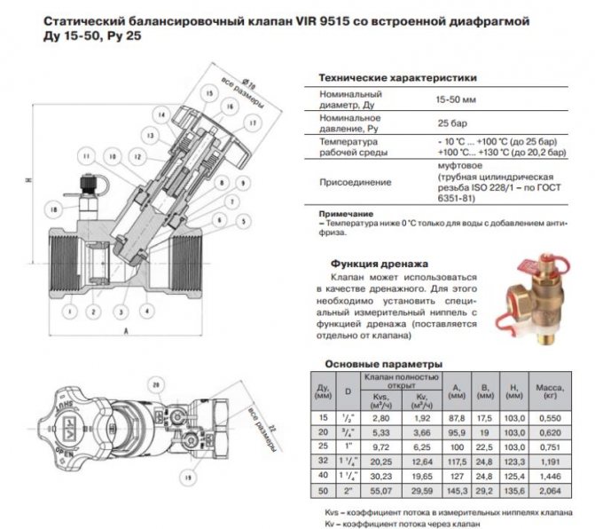
Accompanying documentation indicating equipment parameters
Choosing a mounting method
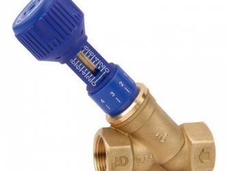
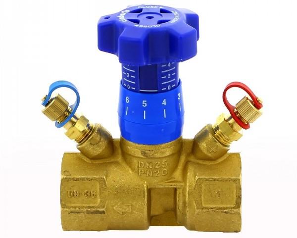
Depending on the installation method, the thermostatic balancing valve can be:
- threaded (figures above), that is, the equipment is connected to the pipes using threads. The most common option for household systems, characterized by relatively low cost, ease of installation and use.
The threaded connection is reusable and, if necessary, the equipment can be replaced or repaired in the shortest possible time. However, when installing the device using a threaded method, it is recommended to use additional means for sealing (FUM tape, Tangit Unilok thread, and so on);
- flanged Mainly used in the construction of industrial pipelines and highways. The flange connection method is simple and tight;
Equipment fixed with flanges
- welded Installation by welding can be carried out both in domestic and industrial conditions. The fastening is the most reliable and airtight. However, installation requires special equipment and minimal skills to work with it. In addition, the resulting connection is permanent and in the event of a malfunction, a full range of replacement work will be required.
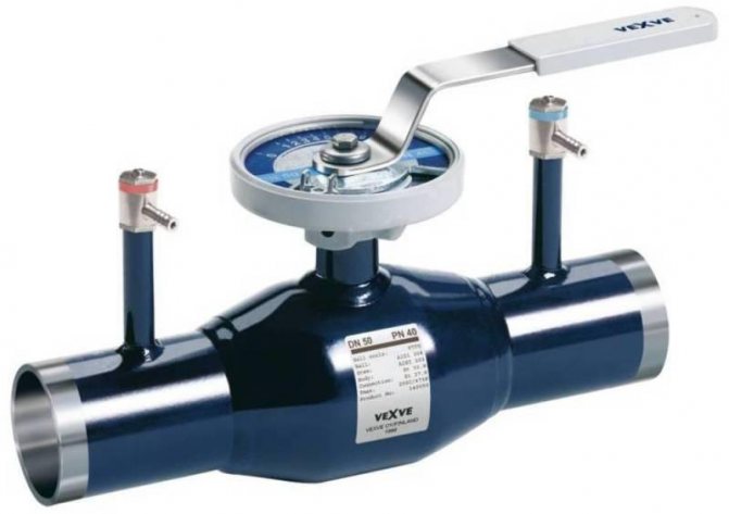
Equipment installed by welding
Popular manufacturers
When choosing, special attention is paid to the selection of the manufacturer, since the reliability and service life of the fittings depend on this parameter.
Experts prefer valves manufactured by the following companies:
- Danfoss (Denmark). The company produces high-quality equipment of various types. Particularly in demand are automatic valves of the Danfoss ASV series (equipment intended for heat and water supply systems) and AB-RM (universal devices), as well as a manually operated model of the Leno™ MSV-BD series, combining the capabilities of a balancing valve and a ball valve;
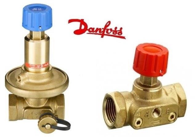
Balancing valves from the Danish company Danfoss
- Cimberio (Italy). Valves of the CIM series are available in different diameters and with different technical parameters. All equipment is complemented by high-strength sealing gaskets, allowing to achieve the maximum level of tightness;
- Broen (Denmark). Manually operated valves of the BALLOREX Venturi series are made on the basis of ball valves and can be used for any type of coolant.
You can also pay attention to the Italian company Valtec, the Swedish company TOUR ANDERSSON, which produces products under the STAD brand, and the Comap company from France.
Installation Features
If you decide to purchase a Danfoss balancing valve, you should first familiarize yourself with the installation features. In order to guarantee the accuracy of measurements, there must be sections of pipe without bends before and after the device. The length of the section will depend on the diameter. Before the valve, the length of the straight pipe should be equal to 5 pipe diameters, after the valve the length should be two diameters or more. If these recommendations are not taken into account when installing a Danfoss balancing valve, the error in measurements can reach 20%.
How to set up a balancing valve for a heating system?
How often do the Housing Office receive questions regarding heating of residential premises? Constantly! Some residents have constant cold in their house, others feel hot, and still others hear irritating sounds from the pipes. But, unfortunately, utility services cannot please all residents at the same time. But there is a solution to this problem, and this is a balancing valve for the heating system.