The purpose of a series of such reviews is to help you make one or another choice when purchasing and to be more prepared when placing an order.
People who deal with the topics of heating and water supply professionally have their own opinion before contacting us, which is why we are aimed at buyers who deal with these tasks from time to time and do not want to waste extra time. And it often happens that an accurate calculation is not particularly necessary, since it can give a difference in indicators that can be neglected. So, let's begin.
How much heat is needed?
A simplified calculation of the need for heat generation in the presence of average thermal insulation indicators of walls, floors, ceilings, windows, doors can be done using the following algorithm:
- Basic value: 40*V, where: V is the volume of the heated space.
- Accommodation addition:
- If you have the first or last floor of a multi-story building, then the resulting value is multiplied by 1.2 -1.3;
- If you have a private house or cottage, then this coefficient is 1.5.
- Addition by structural elements:
- Each standard size window is 100 watts;
- Each entrance or balcony door is 200 watts;
- Ventilation (if equipped) another 300 watts.
Here are the figures for Moscow and the region, so take into account additional coefficients in other territories.
Calculation of heat loss at home
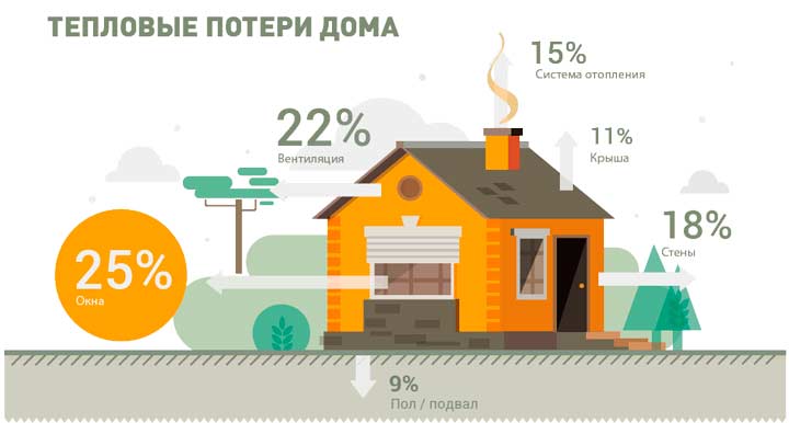
Before calculating a water heated floor, you must first calculate the heat loss of the house. Heat loss is the amount of heat that a room loses per unit of time. To reduce heat loss, heating devices are used, for example radiator heaters, heating pipes, and heated floors. In addition, it is possible to reduce heat loss by installing double-glazed windows and insulating walls with various materials that can retain heat inside the room.
Calculation of heat loss is an important parameter when designing a residential premises. In this case, it is necessary to take into account:
- room area;
- area of all windows;
- ceiling height;
- number of external walls;
- temperature from the outside of the room;
- window type;
- thermal insulation of walls;
- type of room located above.
Basically, heat loss depends on the difference in temperatures outside and inside the room, as well as on the degree of thermal insulation of windows, walls, and partitions. To more accurately calculate heat loss, you can use one of the many online calculators. They are quite simple and easy to use; just enter the required values and the calculation will be done automatically. In such calculators it is possible to calculate heat loss through windows, ceilings, walls, and floors. This will allow you to obtain detailed information on the basis of which the power of the heating equipment should be calculated.
It is generally accepted that a warm floor will cope if the heat loss does not exceed 100 W per meter of area. If this indicator is exceeded, you will have to resort to installing an additional heating device.
How many radiator sections are needed?
The main article on this topic is posted here.
Additionally, we can mention that it is advisable to place the battery itself under the window in order to create a thermal curtain and its width must be at least 50%, and better yet, at least 70% of the width of the window.
If you have a corner room in an apartment and it has convectors both under the window and on the adjacent wall, then it is not advisable to remove any of them. Despite the fact that it would seem there is still one more left. The reason is that in such a room excess heat is required to move the dew point out of the room (in other words, so that the wall does not become damp and mold does not form). This is a frequently occurring problem even when the room seems warm.
It can also be noted that the presence of decorative elements covering the heating device also impairs heat transfer along with non-compliance with the indentations.
Minimum floor surface temperature
This is the temperature of the floor surface directly above the loop pipe. According to regulatory requirements, this parameter should not exceed 35°C.
This is the temperature of the floor surface at an equal distance from the pipes (in the middle).
This parameter is the main criterion for calculating a heated floor in terms of comfort for residents. It represents the average value between the maximum and minimum floor temperature.
According to standards, in rooms with constant presence of people (living rooms, offices, etc.), the average floor temperature should not be higher than 26°C. In rooms with high humidity (bathrooms, swimming pools) or where people are not constantly present, the floor temperature can be up to 31°C.
A floor temperature of 26°C does not provide the expected comfort for the feet. In a private house, where no one has the right to tell the owner what temperature to heat the home at, you can set the average floor temperature to 29°C. At the same time, your feet will feel comfortable warmth. You should not raise the temperature above 31°C - this leads to drying out the air.
How many meters of underfloor heating pipe?
If you already have all the calculations for the desired heat transfer and you know the expected laying step, then the formula for obtaining the total length of the pipe is simple:
L = S/W * K, where:
- L—pipeline length, m;
- S—heating area, m2;
- Ш - layout pitch in meters;
- K - coefficient.
The specified coefficient (K) adds the length of the pipe for its wiring to the collector group and for layout errors. Typically it is 1.1-1.2 depending on how much you are willing to risk being wrong.
The laying step (Ш) is usually a multiple of 5 and in the vast majority of cases corresponds to the indicators from the list: 0.1, 0.15, 0.2, 0.25. With a value less than 0.1, there is a very high chance of breaking the pipeline when it is bent, and with a value greater than 0.25, a “zebra” effect will appear when hot spots combine with cold ones.
It is strictly forbidden to lay threads assembled from several pieces - only as a whole! The only connection should be at the ends of the loops (in the collector groups).
The value obtained in the formula will show your need for the total length, but in order to buy a pipe for a warm floor, you must take into account the following points:
- The pipe is sold in coils of a certain size, and not in pieces calculated by you, so you need to adapt to their size (for example, pipe 16 is most often sold in coils of 100, 160, 200 meters and rarely there are others, such as 400, 600);
- The pipeline in one loop should not be too long, otherwise the coolant in its final part will cool down excessively and will be uncomfortable, as well as there will be excessive flow resistance (for example, it is recommended to make circuits up to 60 meters from threads with a diameter of 16, and with a diameter of 20 to 80 meters);
- It is better not to combine very small rooms into one circuit (an additional risk of damage, as well as the impossibility of separate adjustment).
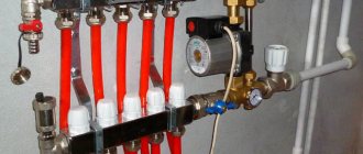
By the way, taking into account the above, you can decide how many outputs you need a collector group for. You simply divide large areas into several circuits, in which there will be 60-80 meters of pipe, and leave one for each small room. Their sum will be the quantity you require. The only thing is that if the heated spaces are on different floors, then it is best to make a separate structure for each of them.
Let's return to our algorithms. If you want to first determine the missing data to understand the packing density mentioned above, then proceed as follows:
- Determine how much heat is required (described above in this article);
- Determine what part of the heat release will be provided by the batteries (described in the article “How many radiator sections are needed per room”);
- Obtain the amount of heat expected from underfloor heating by subtracting from the total requirement the amount provided by the radiators;
- Determine the packing density based on the remaining required heat release.
For the last point, you need to decide what input data you will have:
- Average coolant temperature (usually it is considered to be in the range of 26-28C);
- Pipe diameter (most often it is 16 millimeters, less often - 20);
- Required specific heat transfer. This is the value obtained in step 3 and divided by the area of the expected water floor;
Below are two tables for different surfaces (tiles and linoleum). The tables are compiled taking into account that the thickness of the screed will be 7 cm, and the expected air temperature in the premises will be 20oC.
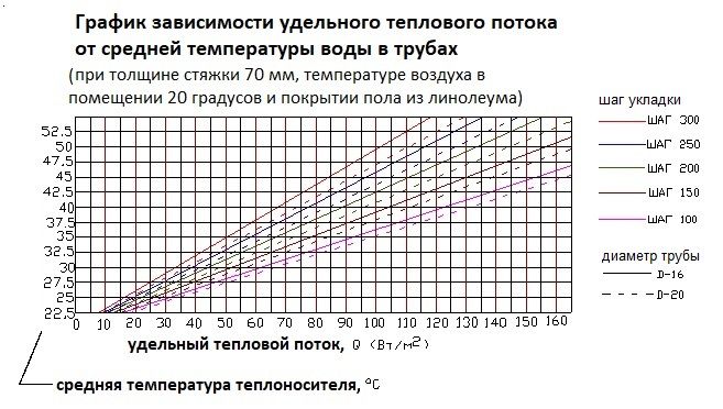
In total, based on this, you can determine the required laying density (pitch) and pipe flow rate for the heated floor.
Is it possible without calculations?
It is not necessary to do calculations. But we still recommend making calculations of the heat loss at home to make sure whether the heated floor will work or not. If the floors pass, we follow a simple method. We lay the heated floor in increments of 15 cm, and in the areas of external walls in increments of 10 cm.
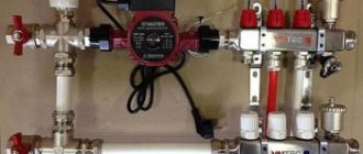
Next, we install room thermostats, connect them to servos on the manifold and enjoy an excellent adjustable heating system.
You can calculate the amount of material required and the pipeline installation diagram manually or using a calculator for calculating a warm, water-based floor. The power of the system, the number of floors of the building, the type of room, free space and other data are taken into account.
The second option is more convenient, because the calculations are made very accurately - a special computer program instantly calculates all the necessary data. Its work is based on the coefficient method: standard, ready-made calculations of heated floors are taken, which change depending on the amendments made (pipe pitch, type and thickness of a specific screed, etc.).
How to set up flow meters?
The easiest way to adjust heated floors is when you remember the length of each loop when laying the pipe and at the same time lay pipes of the same diameter everywhere.
In this case, you can balance the circuits with flow meters according to the following instructions:
- The longest loop is taken and its length is taken as 100 percent;
- We close all circuits except the selected one, and on the contrary, open it completely (both the valve and the flow meter);
- We remember the value on the flow meter (let’s say it’s 5 liters per minute);
- We calculate the percentage of the length of the next loop from the longest. For example, the largest is 60m (100%), and the second is 40m. We get by the proportion formula %=40*100/60=67(%);
- We obtain the required flow rate for this loop - 5 * 67/100 = 3.35;
- We fully open the valve of the desired loop and set the resulting value with the flow meter;
- We repeat this for all contours and get the result.
In general, floor heating system flow meters usually provide the ability to set the fluid flow rate from 0.5 to 5 liters per minute.
In the practical implementation of this approach, the problem of lack of fluid pressure may arise. For example, on the next loop you could not get the desired value even after opening everything completely. You will need to either increase the total pressure by adjusting the mixing unit or by increasing the pump power used. An option when the loop itself is in an abnormal state - i.e. clogged or leaking, we do not consider it. If this does not help, then you need to calculate the share of the flow rate from the value that became when adjusting the current loop.
What to do if you did not remember the length of the laid threads or if you used different diameters for them? How to adjust and connect the underfloor heating manifold with this option?
You can make a more complex calculation based not on the length, but on the volume of coolant that fits there. This volume can be calculated by first blowing out the existing water (if there was any) under air pressure (for example, with a compressor from a car) and refilling it, counting how much water will enter. Use this volume using the same algorithm described above instead of the contour lengths.
Pipe selection and heat transfer
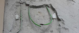
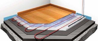
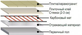
Most often, when installing a warm water floor, as in the photo, a cement screed is poured, which reliably protects pipelines from damage and is characterized by excellent thermal conductivity. The layer of solution above the pipes should be at least 3, and preferably 5 centimeters.
Porcelain stoneware and tiles are considered the optimal choice of coating when installing heated floors, since they have sufficient thermal conductivity and warm up quickly.
To draw a detailed diagram you will need graph paper, a pencil and a ruler. You also need to know the parameters of the room. Taking into account the scale, the places where pipes are planned to be laid are marked on the sheet. Once the drawing is ready, it will be possible to calculate the length of the pipeline. Two meters are added to the obtained value for errors and arrangement of the riser.
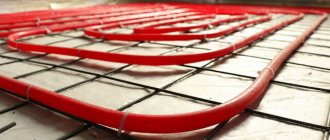
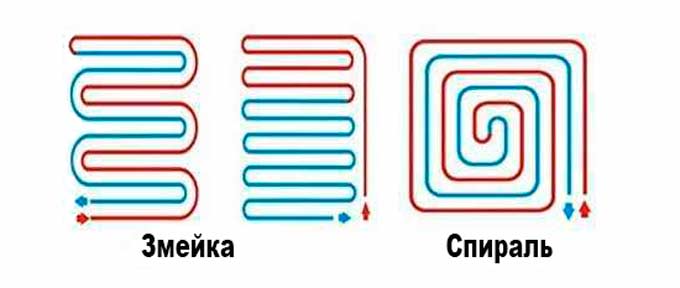
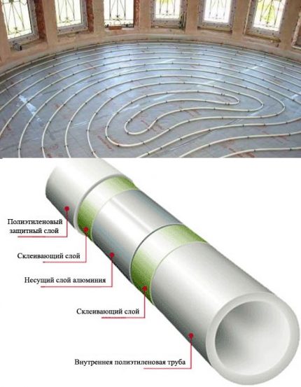
In practice, 4 heating circuit installation schemes are used: snail, corner snake, snake and double snake. In this case, the corner snake and just the snake are laid using sequential technology, and for this reason, in one part of the room the floor will be warmer than in the other. These two options are used only for small rooms.
Due to non-standard operating conditions, high demands are placed on the material and size of the water floor coil:
- chemical inertness, resistance to corrosive processes;
- the presence of an absolutely smooth internal coating, not prone to the formation of limescale build-ups;
- strength - the walls are constantly exposed to the coolant from the inside, and the screed from the outside; the pipe must withstand a pressure of up to 10 bar.
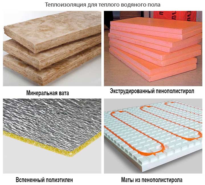
It is desirable that the heating branch have a small specific gravity. The water floor pie already places a significant load on the ceiling, and a heavy pipeline will only aggravate the situation.
According to SNiP, the use of welded pipes in closed heating systems is prohibited, regardless of the type of seam: spiral or straight
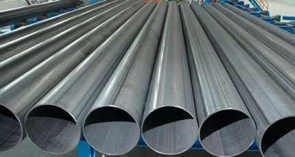
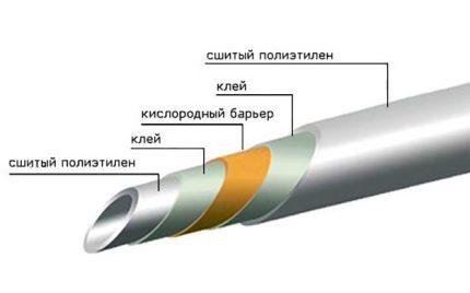
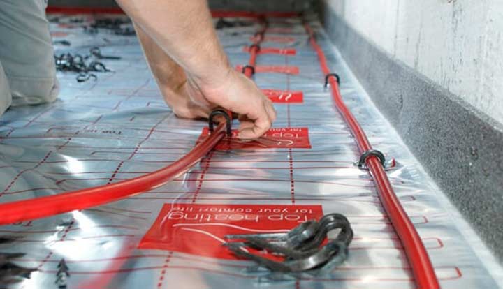
Three categories of rolled pipes meet the listed requirements to one degree or another: cross-linked polyethylene, metal-plastic, and copper.
The material has a mesh wide-cell structure of molecular bonds. Modified polyethylene differs from conventional polyethylene in the presence of both longitudinal and transverse ligaments. This structure increases specific gravity, mechanical strength and chemical resistance.
A water circuit made of PEX pipes has a number of advantages:
- high elasticity, allowing the coil to be laid with a small bend radius;
- safety – when heated, the material does not emit harmful components;
- heat resistance: softening – from 150 °C, melting – 200 °C, combustion – 400 °C;
- maintains structure during temperature fluctuations;
- resistance to damage - biological destroyers and chemical reagents.
The pipeline retains its original throughput - no sediment is deposited on the walls. The estimated service life of a PEX circuit is 50 years.
The disadvantages of cross-linked polyethylene include: fear of sunlight, the negative effects of oxygen when it penetrates inside the structure, the need for rigid fixation of the coil during installation
There are four product groups:
- PEX-a – peroxide cross-linking. The most durable and uniform structure with a bond density of up to 75% is achieved.
- PEX-b – silane cross-linking. The technology uses silanides - toxic substances that are unacceptable for household use. Manufacturers of plumbing products replace it with a safe reagent. Pipes with a hygienic certificate are acceptable for installation. Crosslink density – 65-70%.
- PEX-c – radiation method. Polyethylene is irradiated with a stream of gamma rays or an electron. As a result, the bonds are compacted up to 60%. Disadvantages of PEX-c: unsafe use, uneven cross-linking.
- PEX-d – nitriding. The reaction to create a network occurs due to nitrogen radicals. The output is a material with a crosslink density of about 60-70%.
The strength characteristics of PEX pipes depend on the method of cross-linking polyethylene.
If you choose pipes made from cross-linked polyethylene, we recommend that you familiarize yourself with the rules for installing a heated floor system made from them.
The leader in rolled pipes for installing heated floors is metal-plastic. Structurally, the material includes five layers.
The inner coating and outer shell are high-density polyethylene, which gives the pipe the necessary smoothness and heat resistance. Intermediate layer – aluminum spacer
The metal increases the strength of the line, reduces the rate of thermal expansion and acts as an anti-diffusion barrier - it blocks the flow of oxygen to the coolant.
Features of metal-plastic pipes:
- good thermal conductivity;
- ability to maintain a given configuration;
- operating temperature with preservation of properties – 110 °C;
- low specific gravity;
- noiseless movement of the coolant;
- safety of use;
- corrosion resistance;
- service life – up to 50 years.
The disadvantage of composite pipes is the inadmissibility of bending about the axis. Repeated twisting risks damaging the aluminum layer. We recommend that you familiarize yourself with the correct technology for installing metal-plastic pipes, which will help avoid damage.
In terms of technical and operational characteristics, yellow metal will be the best choice. However, its demand is limited by its high cost.
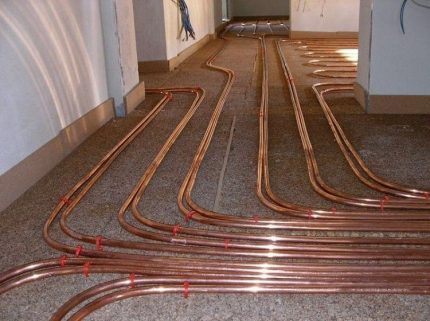
Compared to synthetic pipelines, the copper circuit wins on several points: thermal conductivity, thermal and physical strength, unlimited bending variability, absolute impermeability to gases
. In addition to being expensive, copper piping has an additional disadvantage - the complexity of installation. To bend the contour you will need a press machine or pipe bender.
Sometimes a heating branch is created from polypropylene or stainless steel corrugated pipes. The first option is affordable, but quite rigid in bending - the minimum radius is eight times the diameter of the product.
This means that pipes with a standard size of 23 mm will have to be placed at a distance of 368 mm from each other - an increased laying step will not ensure uniform heating.
Stainless steel pipes have high thermal conductivity and good flexibility. Disadvantages: fragility of sealing rubber bands, creation of strong hydraulic resistance by corrugation
The purpose of the screed over the pipes of heated floors is to absorb the load from people and objects in the heated room and evenly distribute the heat from the pipes over the floor surface.
READ MORE: Heated floor connection diagram
The minimum permissible thickness of the screed above the pipe is 30 mm with reinforcement. With a smaller thickness, the screed will have insufficient strength. Also, the small thickness of the screed does not ensure uniform heating of the floor surface - stripes of hot floor appear above the pipe and cold between the pipes.
It is not worth pouring a screed thicker than 100 mm, because... this increases the inertia of heated floors and eliminates the possibility of quickly adjusting the floor temperature. With a large thickness, a change in the temperature of the floor surface will occur after several hours, or even days.
Based on these conditions, the optimal thickness of the heated floor screed is 60-70 mm above the pipe. Adding fiber and plasticizer to the solution allows you to reduce the thickness to 30-40 mm.