311
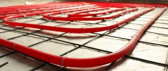
The concept of “warm floor” is a relatively new, but already very popular phenomenon. Today, more and more consumers are using this design when decorating their homes. From our article you will learn how to properly install a heated floor with a mixing unit.
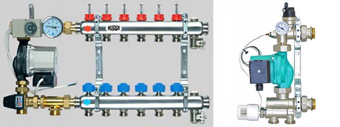
Mixing unit for heated floors
Coolant temperature requirements
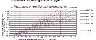
The heating system for underfloor heating is a rather complex set of equipment, the correct assembly and configuration of which largely determines the correct functioning of the entire heating installation. For example, if a boiler is designed to supply a coolant of 70-900C to the radiators, then in underfloor heating circuits operating in parallel in the same rooms, the temperature of the circulating fluid is allowed no higher than 45-500C (max 550C). The exact temperature parameters are derived through engineering calculations of the underfloor heating system. They are designed to ensure the treatment of water in the pumping system in such a way that the heating of floor surfaces, taking into account the structure and material of their coatings, does not exceed:
- in premises with long-term stay of people (offices, residential) – 290C;
- in auxiliary rooms (storage rooms, corridors, dressing rooms) – 300C;
- in bathrooms, bathrooms, swimming pools - 320C.
In addition, the setting of the mixing unit will be performed most optimally if it is possible to achieve a temperature difference between the supply and return of the TP of 5-150C. A decrease in the thermal gradient (Δt) requires an increase in coolant flow, as a consequence of an increase in its circulation rate, which leads to hydraulic losses. A high temperature gradient is already felt tactilely, like a difference in heating of the surface of the floor covering, which causes a certain discomfort.
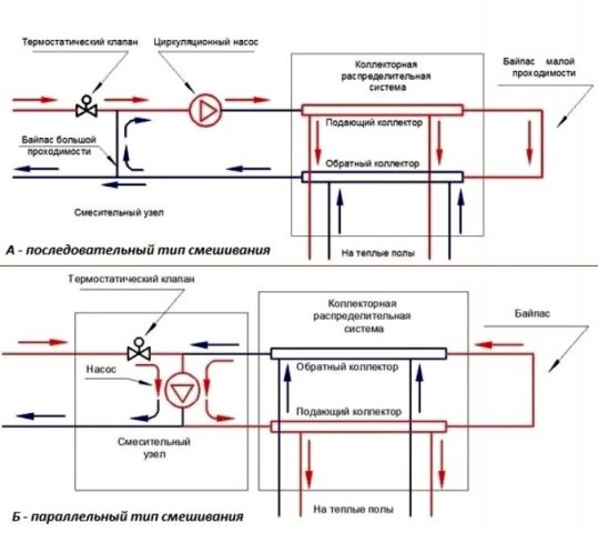
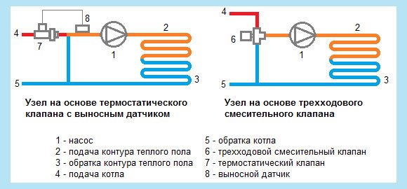
Figure 2
Typical diagrams of pumping and mixing units
Depending on the method of switching on the circulation pump, the following NSU schemes are distinguished:
- sequential - fig. 2a;
- parallel - fig. 2b;
- combined.
In this case, the first two are considered the main ones, and the last scheme, accordingly, represents their hybrid version.
The pump connected in series is used only to prepare the coolant and circulate it in the heated floor circuits. Such a scheme, although it requires the use of two separate pumping units (for the primary and secondary circuits), however, is distinguished by better technological indicators than the parallel one. In professionally manufactured TP systems, the assembly of the pumping unit is often carried out with the sequential activation of the pump. It should be taken into account that the efficiency of such an assembly significantly depends on the correctness of its calculations and settings.
The advantage of connecting a pump in parallel is the ability to use just one unit to circulate the coolant in the primary and secondary circuits. On the one hand, this simplifies assembly, but on the other, it requires the installation of more powerful pumping equipment. If you make a mixing unit for a small household system yourself, then by choosing a parallel arrangement, it is easier to avoid critical mistakes that can negatively affect the operation of the water heated floor.
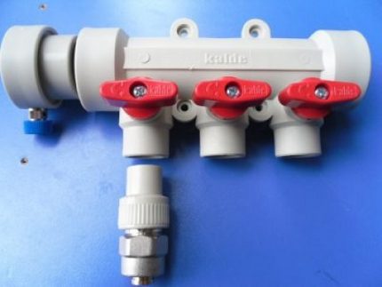
In both parallel and series LSU assemblies, the use of thermostatic two-way (Fig. 2-5 and 7) or three-way (Fig. 1, 8 and 9) valves is practiced. Schemes with thermostats of the first type are recommended for use in rooms with TP areas of several tens of square meters. Therefore, they are quite suitable for organizing underfloor heating in an average typical apartment. The coolant is mixed in them after a two-way valve directly in the circulation flow of the heated floor system.
Three-way thermostats are themselves mixing devices. Inside their housings there is a controlled admixture of coolant from the primary circuit to the circulating flow from the TP system. Three-way thermostatic shut-off and control valves are recommended for installation in large heated areas measuring hundreds of square meters.
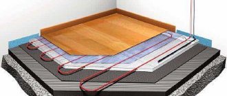
Mixing unit
Installation of a warm water floor.
The mixing unit is needed exclusively for water-based floor structures, since they contain the same coolant as in heating radiators. In most cases, the heating system is organized as follows: a boiler, a coolant for heating, the design of high-temperature radiators, the required number of circuits.
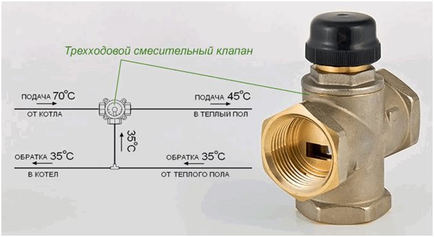
The boiler will heat the water to the temperature required for the radiators. In most cases, this is 95 ° C, but sometimes radiators with a temperature of 70-80 ° C are installed. According to sanitary standards, the floor base should not heat up more than 31 ° C. If you take into account the thickness of the screed in which the floor structure pipes are laid, as well as the type of coating base of the floor, the liquid in the tubes should be heated to approximately 40-55 ° C. It should be understood that liquid cannot be sent directly from the boiler to the heating system, since its temperature is high. To cool the liquid at the entrance to the circuit, you should use a heated floor mixing unit. It will mix the hot coolant and the cooled coolant from the return pipe of the heated floors. As a result, the average temperature will become lower, after which the liquid will flow into the circuit. As a result, all available heating devices will work correctly: hot water will be supplied to the radiators at a temperature of 95°C, and to the heated floor circuit at a temperature of 55°C.
It is possible not to use a mixing unit if the heating in the entire apartment or private house is carried out using low-temperature circuits, while the heated liquid will heat the coolant exclusively for the heating system to the required values. An example of such a design is an air pump. If the heat source will heat water not only for heated floors, then a mixing unit should be installed.
Why use a mixing unit?
The most important difference between the operation of radiators and convectors and underfloor heating is the temperature of the working fluid.
So, for radiators, a water temperature of 60 to 90 degrees is used, which directly comes out of the boiler. But for a heated floor, the recommended liquid temperature is approximately 30-40 degrees.
The operating principle is similar to the operation of an ordinary mixer.
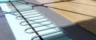
If we connect the circuits to the collector along with the batteries, then the warm floor will receive a large amount of heat, and this is not acceptable for a number of reasons.
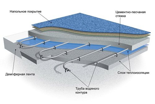
- Since the screed layer above the pipes is approximately 3-6 cm, high temperatures will lead to cracking and deformation of the layer.
- Pipes that are located inside the screed will experience greater load, which will lead to local stresses, since at high temperatures the linear expansion is much greater, and the pipes are limited by a layer of concrete screed. All this will lead to rapid failure of the pipes.
- Floor coverings do not like hot surfaces; they begin to delaminate and crack (laminate, parquet boards, parquet). In the case of ceramic tiles, peeling is possible. Linoleum loses its shape, dries out and becomes deformed.
- An overheated floor surface disrupts the microclimate of the premises.
- If we assume that the floor surface will warm up to 50 degrees, then it will be impossible to walk on it barefoot.
From the above it follows that the mixing unit is simply not replaceable. Since hanging a separate boiler on a “warm floor” system is simply stupid and not profitable.
And making minor changes to the heating system layout (if the heating is already installed) is not difficult. And if you are installing a circuit from scratch, then this device should be provided in advance.
It should be said that there are boilers on sale that immediately provide technology for heating and removing two liquid carriers of different temperatures at once. This equipment is very expensive and is not popular.
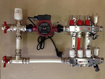
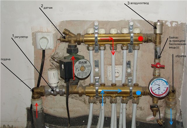
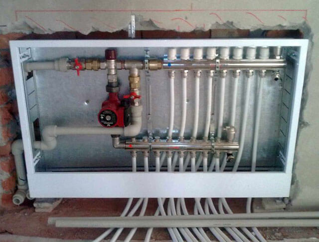
Design of the pumping and mixing unit
A pumping and mixing unit (PMU) is a complex device designed to constantly and stably maintain a given coolant temperature.
As well as uninterrupted coolant circulation in the system. If we use a combined heating method, then we must use a pumping and mixing unit for a heated floor.
The NSU should be considered together with the collector block. Since we said that this is a complex device, it therefore consists of several mechanisms.
Let's look at each one separately:
- The pump is designed to maintain constant circulation of the coolant. Due to it, the hot liquid and the cooled return liquid are mixed, after which it pushes the resulting composition through the system. It is advisable to use a circulation pump with switching operating modes.
- The valve with thermostat is designed to control the temperature. There is a two-way valve; it is used when adjustment is not required. The three-way mixing valve is used for its stability and for large manifolds and long circuits. They can be of mixing and separation type, with a thermal head and a built-in sensor. It is recommended to use it with a remote sensor, they are more accurate. Recently, automatic valves that can be programmed have been widely used.
- Flow regulator. There are two types.
- First. The balancing valve has a scale from 1 to 10. These indicators depend on the length of the pipes. That is, while laying the contours, their length is measured and during adjustment the balancers are set according to the measurements. 10 corresponds to the longest length, and 1 to the shortest.
- Second. Float type, has a scale from 1 to 5. It looks like a transparent glass or flask. The numbers indicate consumption in liters per minute. A float (usually a single color) is placed inside the flask, which moves around the school depending on the pressure. The disadvantages include quick release due to scale.
- The collector block is used to connect several underfloor heating circuits. It is called a block because it combines a return collector and a supply. Collectors are designed for a certain number of connections.
These are the main components of the NCS, but the components and equipment can be varied. All components can be purchased separately and assembled a pumping and mixing unit for heating with your own hands.
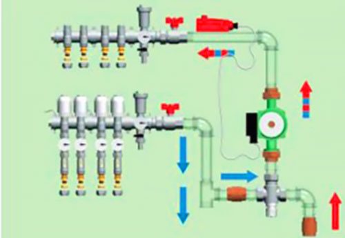
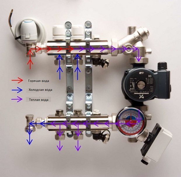
Principle of operation
Construction of a mixing unit for a water floor.
The operation of the structure can be described as follows: the hot coolant will reach the collector of the heating structure and rest against the safety damper with a thermostat. If it is heated more than necessary, the damper will operate and open the supply of cold return pipe, resulting in mixing - mixing of hot and cold water. As soon as water of the required temperature is received, the damper will operate again and shut off the supply of hot coolant. You should know that the operation of this device can be organized in several ways.
The collector unit can be used not only to change the temperature of the coolant, but also to ensure circulation in the system. Therefore, such a bundle should consist of the following components:
- Damper for protection. It will feed the heating system with hot fluid as much as necessary, as a result the inlet temperature will be controlled.
- Circulation pump. This device will move fluid in the structure contour at a specific speed. As a result, heating of the entire area of the structure will be the same.
Water supply in the mixing unit.
The mixing unit for a heated floor may consist of the following elements: shut-off dampers and elements for air exhaust.
The mixing unit is always mounted before the system circuit, but the location of its installation may be different. For example, it can be placed in a room with a heated floor, in a room on the separation of collector structures that go to circuits with low and high temperatures. If there are several rooms with heated floors, then mixing units will need to be installed in each room or in a cabinet located next to the collector.
Various dampers can be installed in the design for protection. In most cases, three-way and two-way valves are used.
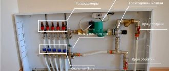
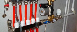
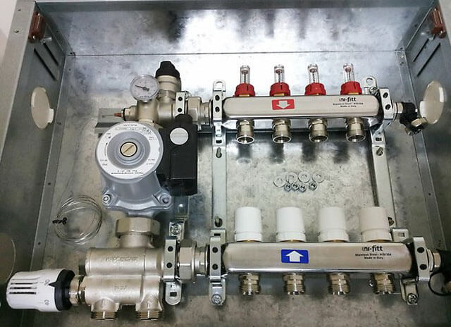
Equipment
The mixing unit is a complex mechanism, responsible for maintaining a stable water temperature and for its continuous circulation. It is included in the collector block and consists of a number of mechanisms.
Pump
The main function of the pump is to create a constant movement of water through the pipeline. It supplies and returns it through the collector and floor branches. Its main indicators are pressure and productivity.
If calculated correctly, the pump will ensure that the hydraulic resistance in the floor line is overcome. It is recommended to use a device with an automatic operating mode switch.
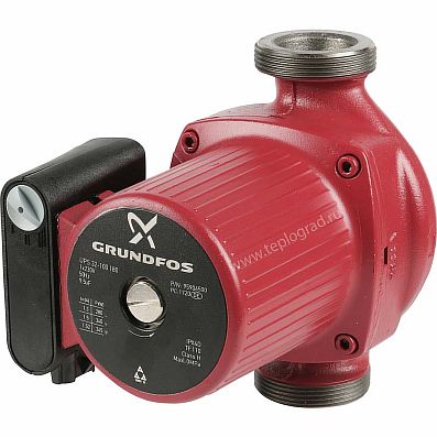
Circulation pump
Flow regulator
Flow meters are:
- Primary circuit balancing valve (float) - it is responsible for the amount of coolant that enters the main line from the primary high-temperature source. The flow is regulated due to its throughput. The adjustment is made by a valve with a head; it is rotated with a key. Adjustment is also carried out by the thermostat valve, which is controlled by a remote sensor.
- Balancing valve of the secondary circuit - it is adjusted depending on the size of the heated area. By opening and closing the control valve, the proportions of the heated and cooled flow change. Closing the balancing valve of the secondary circuit return leads to an increase in the supply of hot coolant from the boiler, and this leads to an increase in thermal conductivity.
The degree of opening is adjusted using a scale printed on the flask. It determines the throughput of the device in m3 per hour.
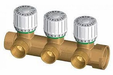
Balancing valve
Bypass valve
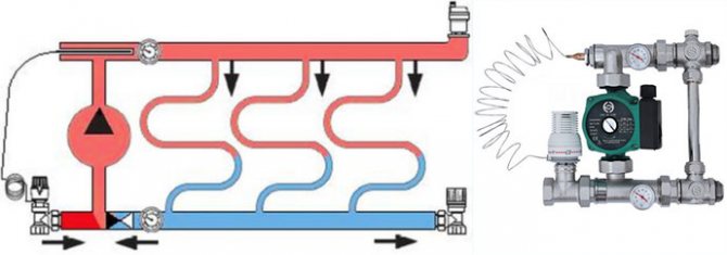
The bypass, together with the bypass valve, helps ensure uninterrupted operation of the pumping equipment when the backpressure mode is in effect - when the circulation of liquid through the floor pipeline is completely or partially stopped. This can happen if the loop valves on the comb are closed manually or using taps.
As a result, the resistance to water flow increases, as well as the load on the mechanism. The pressure level in the system increases and the bypass valve opens.
The coolant flows through the bypass pipes and the pump, thereby closing a small circulation cycle. This leads to the elimination of emergency situations.
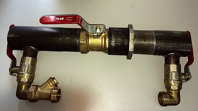
Bypass
Auxiliary elements
Auxiliary elements are also responsible for the functions of monitoring and maintaining the efficient operation of the pumping and mixing structure. This:
- thermometer - controls the temperature of the coolant;
- air vent - air is removed from the system through it;
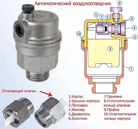
Air vent
- drainage taps, their purpose is to drain water;
- check ball valve - prevents the flow of coolant in the opposite direction.
Collector block
Collector group - heated floor circuits are connected to it, calculated for a certain number of branches. It includes feed and return combs.
Examples of pumping and mixing units: operating principle
There are many schemes for mixing units, but we tried to select only the most understandable and easy to make with our own hands. All schemes are based on the same orientation - on the left side is the supply and return pipe supply, on the right side is the outlet to the underfloor heating manifold. Specifically, the collector itself can be connected to the pumping and mixing unit or located at a certain distance. This depends on the amount of space allocated for the equipment.
Example 1
A three-way thermal mixing valve must be installed in the pumping and mixing unit instead of the usual one. This device is controlled by a thermal head equipped with a remote sensor (its position remains the same).
The mixing of water flows occurs in a three-way valve. The valve works on the principle that when the stem changes its position, one passage begins to open slightly, and the other begins to close.
The three-way valve can be controlled not by a separate thermal head - many models are equipped with built-in temperature sensors. But some experts argue that a remote sensor is more correct and with it the system functions much better.
This example of connecting a unit assumes the use of a check valve installed on the bypass. It must be installed if the automation additionally “commands” the circulation pump. If you do not install a check valve, then when the circulation is idle, the bypass will turn into an ordinary uncontrolled jumper, and this will negatively affect the balance of the heating system and the operation of its other components. But if the pump operates constantly, this valve may not be installed, since it can become a source of additional hydraulic resistance.
Self-installation of the mixing unit
There is no exact assembly diagram for the unit. Below you will see the assembly using the first diagram as an example.
- Lay out all the components of the mixing unit in front of you.
- Remove the screws from the pump. Without tearing the pump parts apart, carefully rotate the upper “half” relative to the lower one by half a turn. Align the holes for the screws and screw them in.
- The described circuit consists of three thermometers. The mixing group involves the use of dial thermometers with probes. To check if the reading is correct, test it with another thermometer. If deviations are observed, the thermometers need to be adjusted. There is a calibration screw on the end of the probe (under the protective cap). If you turn it, the thermometer needle is set to the correct value.
- Now you can assemble the mixing unit. Attach a tee to the shut-off ball valve with an “American” connection on which the thermometer will stand.
- Connect the branch pipe of the mixing unit to the other outlet of the tee.
- Install a bypass. The procedure involves screwing the pipe from the “American” one onto the lower inlet of the thermostatic valve.
- Screw the tee to the fitting from below. The tee outlets indicate the flow direction.
- Connect the left outlet of the tee to the shut-off ball valve using an American fitting. If necessary, you can install a check valve between the tap and the tee.
- Place a thermometer tee on the opposite section from the tee. After successfully installing the thermometer, you can begin to assemble the upper right part of the mixing assembly. Its extreme section should consist of a shut-off valve, a straight pipe, a tee for mounting a thermometer and a fitting from the circulation pump kit.
- Install a shut-off valve on the lower “branch” running from the collector with the “return” to the bypass.
- Place the second fitting in the right valve pipe. Now all that remains is to install the pump.
- Place the standard gasket in the union nut, then screw the nut onto the pump inlet, but do not compress it yet.
- Carry out a similar action with the outlet of the pump.
- Place the pump in the required position and secure the nuts.
- Tighten all connectors.
- Install the assembled mixing unit in a selected location, connect it to the heating circuit pipes and to the underfloor heating manifolds.
Making a homemade collector
To make a manifold from polypropylene pipes, it is recommended to use structures with a diameter of 32 mm or 25 mm, corresponding tees and shut-off valves.
How many underfloor heating loops will be connected, how many tees and valves will be needed for the manifold. You will also need to purchase a circulation pump and valve for the mixing unit.
If the water heated floor system does not need serious automatic regulation, you can make the collector yourself or purchase a simple model with conventional shut-off valves
To solder pipes, you need a special soldering iron, as well as at least minimal experience in using such equipment. The supply and discharge sections of the collector are formed from tees and pipes. The pipe sections must be very short so that the tees are separated by very little space.
After this, stop valves are soldered, as well as fittings for connecting to the pump, etc. Such a simple device will not be expensive if you do not install flow meters and other control elements.
But a more advanced plastic collector is easier to buy than to make; the cost of such a device is low.
Features of the arrangement of mixing units
A do-it-yourself mixing group for underfloor heating, in which warm liquid is mixed with cold liquid, is installed next to the heater. If the hydraulic elements of the system are connected using elastic tubes, then the unit must be firmly fixed to the wall.
Before starting installation, you must make sure there is space for unobstructed access to the mixer parts. The control valve should be placed in the area where the coolant enters the heater.
When choosing a pipe material, you need to make sure that it can withstand the temperature of the incoming fluid. Experts recommend purchasing polymer pipe products. It should be remembered that galvanized pipes cannot be used for glycol-water solutions.
It is desirable that the shut-off elements be made of brass and bronze, the tubes made of black steel, and the pumping equipment made of cast iron. Steel products for the system from the outside are primed and painted at the factory.
When choosing the location and connection of the unit, you need to remember about air bubbles that may appear from the outlet of the boiler circuit. It is also necessary to exclude the possibility of water or condensation getting on the system elements that are under voltage.
Taking into account the above information, we can conclude that the mixing unit should be selected individually so as to ensure maximum ease of use of the floor surface heating structure. You can choose the connection diagram yourself or purchase a completely ready-made design.
Three-way valve for mixing unit. Its place and meaning
The main work in the operation of the pumping and mixing unit is played by a three-way valve or an automated analogue of the device, a three-way valve. Usually, mixing units equipped with similar devices are already on sale. If you decide to assemble the complex yourself, decide on the functionality of the valve and how it should work.
By default, valve models are configured for certain temperature parameters. If you wish, you can independently configure the device for your own heating system. To do this, simply move the thermal head of the valve to the desired position.
Important! Three-way valves have a low flow rate of only 2 m3 per hour. Therefore, it is optimal to use three-way valves for mixing the coolant when working with short-term water circuits. (For heating areas no more than 50m2).
To work with long-distance water circuits, three-way valves are used, designed for large volumes of water (up to 4 m3 per hour). As a rule, such devices have both a manual control option and are equipped with servo drives. Such devices are used successfully for the operation of heated floors in rooms with areas of more than 100 m2.
Types of mixers for heated floors
Faucets of different models can have many differences, but the most important one is which safety valves are used in a particular case. Most often, mixing units are equipped with two- and three-way valves.
The two-way valve design includes a thermostatic head and a liquid sensor that detects the temperature in the system and regulates the flow of coolant depending on the information received. A mixer equipped with such a valve operates on a simple principle: the basis for mixing the coolant is cold water, to which hot water coming from the boiler is mixed. Thanks to this principle, overheating of the heated floor is prevented and its service life is increased.
The two-way valve has a small throughput, which ensures a smooth change in the state of the coolant - that is, there are no sudden overloads in the system. Such valves are quite convenient, but it is advisable to use them only in rooms with a total area of no more than 200 sq.m.
A three-way valve is a more universal device that combines the functions of supply and adjustment. The principle of operation of the mixing unit for a heated floor in this case is completely opposite to the previous one - heated water constantly circulates in the system, to which a certain volume of cold water is added to mix the coolant.
The design of three-way valves can include servo drives connected to a thermostat, which provide adjustment of the coolant temperature depending on the external temperature. For dosed liquid supply, a damper is used, located perpendicular to the pipes coming from the boiler and the return circuit. Three-way valves are ideal for systems used to heat large houses and have a large number of separate circuits.
Three-way valves have a couple of disadvantages:
- A heated floor can overheat due to a temperature jump if the volume of hot coolant significantly exceeds the volume of cold fluid;
- Three-way valves have a significant flow capacity, so even a small change in the position of the damper can cause overheating.
The system, equipped with automation that monitors external weather conditions, is quite convenient and allows you to proactively eliminate a number of problems. As soon as the weather outside changes noticeably, the temperature sensor independently sends a signal to the system about the need to increase or decrease the intensity of coolant supply.
Automation is of particular importance in large buildings - it is very difficult to manually adjust the heating of a large area, especially in conditions of dynamically changing weather. The outside temperature is monitored every minute and the damper blade changes its position if necessary. If there is no one in the house for a certain period of time, then you can set the heating to maintain a minimum temperature, which allows you to save on energy resources.
Installation of pumping and mixing unit. Connection methods
When assembling a heated floor in your home, the hardest work is installing the screed. However, connecting water floors to a heating system is also not an easy task and requires certain knowledge. As a rule, the pump unit, mixer and manifold are installed after the installation of heating water circuits has been completed. Mixing stations are connected in a clear sequence. Each device and device must have its own place, which determines the functionality of the devices.
The equipment is installed in a manifold cabinet, in a heated room or next to it, in close proximity. All connections must be made in accordance with technology. For connection, a threaded connection, cold welding or coupling connections are used. When assembling the mixer and pump group with your own hands, try to achieve short and convenient connections that provide easy access to each structural element.
For connection and normal functionality of the unit, it is necessary to observe the correct arrangement of pipes and the settings of each element of the system:
- balancing valve (calculation of its installation location is required);
- circulation pump (feed speed adjustment required);
- balancing each branch of the heating circuit;
- bypass, three-way valve (requires adjustment in manual or automatic mode);
- carry out diagnostics of the finished unit, already fully assembled.
All connections must meet the requirements of thermal and hydraulic calculations. It is appropriate to recall here that before proceeding with the assembly and installation of the pumping and mixing unit, it is important to select the right equipment. Pump power, diameter and capacity of three-way valve. The number of water circuits plays a role in the selection of combs for the manifold group. Air vents and bleed valves must also be installed in certain places.
Author of the article Oleg Borisenko Similar posts
What you need to know about heated floors to make the right choice
Floor coverings for underfloor heating systems: linoleum and laminate
The main thing about thermostats - the control elements of underfloor heating systems Leave a comment Cancel reply
Name *
Email *
Comment Comments (2)
textarea>