The importance of air exchange
Depending on the size of the room, the air exchange rate should be different.
The task of any ventilation is to ensure an optimal microclimate, humidity level and air temperature in the room. These indicators affect a person’s comfortable well-being during work and rest.
Poor ventilation leads to the proliferation of bacteria that cause respiratory tract infections. Food products begin to spoil quickly. Increased humidity levels provoke the appearance of fungus and mold on walls and furniture.
Fresh air can enter the room naturally, but compliance with all sanitary and hygienic indicators is possible only with a high-quality ventilation system. It must be calculated for each room separately, taking into account the composition and volume of air, design features.
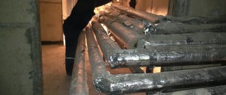
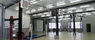
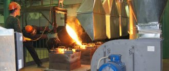
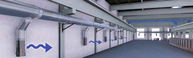
For small private houses and apartments, it is enough to equip shafts with natural circulation of air flows. But for industrial premises and large houses, additional equipment is required in the form of fans that provide forced circulation.
When planning a building for an enterprise or public institution, the following factors must be taken into account:
- high-quality ventilation should be in every room;
- it is necessary that the composition of the air complies with all approved standards;
- enterprises require the installation of additional equipment that will regulate the air speed in the air duct;
- For the kitchen and bedroom it is necessary to install different types of ventilation.
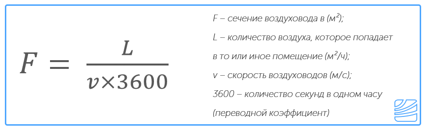
In order for the air exchange system to meet all requirements, it is necessary to calculate the air speed in the air duct. This will help you choose the right device.
Basic formulas for aerodynamic calculations
The first step is to make an aerodynamic calculation of the highway. Let us remind you that the main air duct is considered to be the longest and most loaded section of the system. The fan is selected based on the results of these calculations.
When calculating the main branch, it is desirable that the speed in the air duct increases as it approaches the fan!
Just don’t forget about linking the remaining branches of the system. It is important! If it is not possible to make connections on the branches of the air ducts within 10%, you need to use diaphragms. The diaphragm resistance coefficient is calculated using the formula:
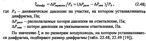
If the discrepancy is more than 10%, when a horizontal air duct enters a vertical brick duct, rectangular diaphragms must be placed at the junction.
The main task of the calculation consists of finding the pressure loss. At the same time, I select the optimal size of the air ducts and control the air speed. The total pressure loss is the sum of two components - pressure loss along the length of the air ducts (due to friction) and losses in local resistance. They are calculated using the formulas
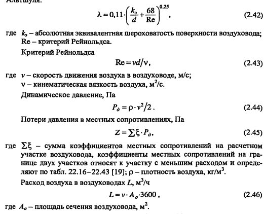
These formulas are correct for steel air ducts; for all others, an correction factor is introduced. It is taken from the table depending on the speed and roughness of the air ducts.
For rectangular air ducts, the calculated value is the equivalent diameter.
Let's consider the sequence of aerodynamic calculation of air ducts using the example of offices given in the previous article using formulas. And then we’ll show you what it looks like in Excel.
Calculation example
According to calculations, the air exchange in the office is 800 m3/hour. The task was to design air ducts in offices no more than 200 mm high. The dimensions of the room are given by the customer. Air is supplied at a temperature of 20°C, air density 1.2 kg/m3.
It will be easier if the results are entered into a table of this type
First we will do an aerodynamic calculation of the main line of the system. Now everything is in order:
- We divide the main line into sections along the supply grilles. We have eight grates in the room, each with a capacity of 100 m3/hour. There were 11 sections. We enter the air flow at each section into the table.
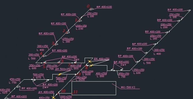
- We record the length of each section.
- The recommended maximum speed inside the duct for office premises is up to 5 m/s. Therefore, we select the size of the air duct so that the speed increases as it approaches the ventilation equipment and does not exceed the maximum. This is done to avoid noise in ventilation. Let’s take an air duct of 150x150 for the first section, and 800x250 for the last section.
V1=L/3600F =100/(3600*0.023)=1.23 m/s.V11= 3400/3600*0.2= 4.72 m/s
We are satisfied with the result. We determine the dimensions of the air ducts and the speed using this formula in each section and enter them into the table.
- We begin calculating pressure losses. We determine the equivalent diameter for each section, for example the first dе=2*150*150/(150+150)=150. Then we fill in all the data necessary for the calculation from the reference literature or calculate: Re=1.23*0.150/(15.11*10^-6)=12210. λ=0.11(68/12210+0.1/0.15)^0.25=0.0996 The roughness of different materials is different.
- Dynamic pressure Pd=1.2*1.23*1.23/2=0.9 Pa is also recorded in the column.
- From Table 2.22 we determine the specific pressure loss or calculate R=Pd*λ/d= 0.9*0.0996/0.15=0.6 Pa/m and enter it in a column. Then at each section we determine the pressure loss due to friction: ΔРtr=R*l*n=0.6*2*1=1.2 Pa.
- We take local resistance coefficients from reference literature. In the first section we have a grille and an increase in the air duct in the sum of their CMC is 1.5.
- Pressure loss in local resistances ΔРм=1.5*0.9=1.35 Pa
- We find the amount of pressure loss in each section = 1.35+1.2=2.6 Pa. And as a result, the pressure loss in the entire line = 185.6 Pa. by that time the table will look like
Next, the remaining branches are calculated using the same method and linked. But we’ll talk about this separately.
When linking branches, the discrepancy in pressure loss should be no more than 15% if the air enters one room (workshop) and no more than 10% if it enters different rooms
After this, the aerodynamic calculation can be considered complete. For round air ducts, the calculation principle is the same, only the equivalent diameter is equal to the diameter of the air duct.
Rules for determining air speed in an air duct
As the diameter of the pipes increases, the air speed decreases and the pressure drops
The air flow rate in ventilation is directly related to the level of vibration and noise in the system. These indicators must be taken into account when calculating behavior. The movement of the air mass creates noise, the intensity of which depends on the number of pipe bends. Resistance also plays a big role: the higher it is, the lower the speed of movement of air masses will be.
Noise Level Standards
Based on sanitary standards, the maximum possible sound pressure levels in the premises are established.
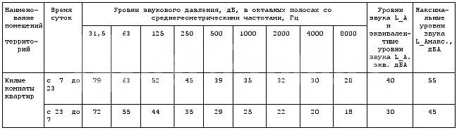
Exceeding the listed parameters is possible only in exceptional cases when it is necessary to connect additional equipment to the system.
Vibration level
The level of noise and vibration depends on the inner surface of the pipe
During operation of any ventilation device, vibration is generated. Its performance depends on the material from which the air duct is made.
Maximum vibration depends on several indicators:
- the quality of gaskets that are designed to reduce vibration levels;
- pipe manufacturing material;
- duct size;
- air flow speed.
General indicators cannot be higher than those established by sanitary standards.
Air exchange rate
Air masses are purified through air exchange; it is divided into forced and natural. In the second case, it is achieved by opening windows, vents, in the first through the installation of fans and air conditioners.
For an optimal microclimate, air changes should occur at least once an hour. The number of such cycles is called the air exchange rate. It must be determined in order to establish the speed of air movement in the ventilation duct.
The frequency rate is calculated using the formula N=V/W, where N is the frequency rate per hour; V is the volume of air that fills a cubic meter of room per hour; W is the volume of the room in cubic meters.
Stage two
Here the aerodynamic drag values are calculated. After selecting standard sections of air ducts, the value of the air flow speed in the system is specified.
Calculation of pressure loss due to friction
The next step is to determine the specific pressure loss due to friction based on tabular data or nomograms. In some cases, a calculator can be useful for determining indicators based on a formula that allows calculations with an error of 0.5 percent. To calculate the total value of the indicator characterizing the pressure loss over the entire section, you need to multiply its specific indicator by the length. The roughness correction factor should also be taken into account at this stage. It depends on the absolute roughness of a particular duct material, as well as the speed.
Calculation of the dynamic pressure indicator on a segment
Here an indicator characterizing the dynamic pressure in each section is determined based on the values:
- air flow speed in the system;
- air mass density under standard conditions, which is 1.2 kg/m3.
Determination of local resistance values in areas
They can be calculated based on local resistance coefficients. The obtained values are summarized in tabular form, which includes data from all sections, not only straight sections, but also several shaped parts. The name of each element is entered in the table, and the corresponding values and characteristics are indicated there, by which the local resistance coefficient is determined. These indicators can be found in the relevant reference materials on the selection of equipment for ventilation units.
If there are a large number of elements in the system or in the absence of certain coefficient values, a program is used that allows you to quickly carry out cumbersome operations and optimize the calculation as a whole. The total resistance value is determined as the sum of the coefficients of all elements of the segment.
Calculation of pressure losses at local resistances
Having calculated the final total value of the indicator, we move on to calculating pressure losses in the analyzed areas. After calculating all sections of the main line, the resulting numbers are summed up and the total resistance value of the ventilation system is determined.
Algorithm and formulas for calculating air speed
Option for calculating air speed in pipes of different diameters
You can calculate the air flow yourself, taking into account the conditions and technical parameters. To calculate, you need to know the volume of the room and the multiplicity rate. For example, for a room of 20 square meters, the minimum value is 6. Using the formula gives 120 m³. This is the volume that must move through the channels within an hour.
The speed in the duct is also calculated based on the cross-section diameter parameters. To do this, use the formula S=πr²=π/4*D², where
- S – cross-sectional area;
- r – radius;
- π – constant 3.14;
- D – diameter.
Once the cross-sectional area and air flow rate are known, its speed can be calculated. To do this, use the formula V=L/3600*S, where:
- V – speed m/s;
- L – flow rate m³/h;
- S – cross-sectional area.
The noise and vibration parameters depend on the speed in the air duct cross-section. If they exceed the permissible standards, you need to reduce the speed by increasing the cross-section. To do this, you can install pipes from a different material or make a curved channel straight.
Air flow calculation
It is important to correctly calculate the cross-sectional area of any shape, both round and rectangular. If the size is inappropriate, it will be impossible to ensure the desired air balance. An air duct that is too large will take up a lot of space. This will reduce the space in the room and cause discomfort to residents. If the calculation is incorrect and a very small channel size is chosen, strong drafts will be observed. This occurs due to a strong increase in air flow pressure.
Sectional calculation
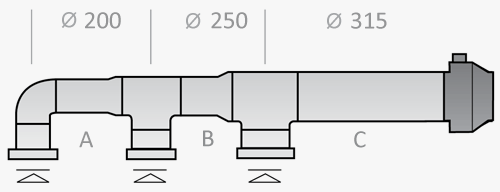
When a round duct changes to a square one, the speed will change
To calculate the speed at which air will flow through the pipe, you need to determine the cross-sectional area. The following formula is used for calculation: S=L/3600*V, where:
- S – cross-sectional area;
- L – air flow in cubic meters per hour;
- V – speed in meters per second.
For round air ducts, it is necessary to determine the diameter using the formula: D = 1000*√(4*S/π).
If the duct is rectangular rather than round, instead of the diameter, you need to determine its length and width. When installing such an air duct, the approximate cross-section is taken into account. It is calculated by the formula: a*b=S, (a – length, b – width).
There are approved standards according to which the ratio of width to length should not exceed 1:3. It is also recommended to use tables with standard dimensions offered by air duct manufacturers.
Round ducts have an advantage. They are characterized by a lower level of resistance, so during operation of the ventilation system the level of noise and vibration will be minimized.
Material and cross-sectional shape of air ducts
Round ducts are most often used in large enterprises. This is due to the fact that their installation requires many square meters of room space. Rectangular sections are most suitable for residential buildings; they are also used in clinics and kindergartens.
Steel is most often used to make pipes. For a round section it should be elastic and hard, for rectangular ones it should be softer. Pipes can be made of textile and polymer materials.
Choosing the right ventilation pipes
The air duct calculation is done taking into account the size of the room
Before designing a ventilation system, all speed, noise and vibration parameters must be taken into account. It is necessary to make calculations taking into account the area of the room to ensure high-quality air exchange. The material of manufacture also plays a big role in the choice.
Galvanized steel air ducts are considered the most universal. They can be operated at high temperatures and pressures. They can be used for any climate zones.
Air ducts made of black steel are most often used in industry. They are heat and fire resistant, but are subject to severe corrosion.
Aluminum corrugated air duct has a high degree of flexibility, strength and elasticity. The material is resistant to high temperatures. But such an air duct has a drawback. Due to the high aerodynamic resistance, there is a lot of noise during operation.
Plastic air ducts are distinguished by their high strength, long service life and ease of installation. They are popular due to their low cost and light weight. The downside is low resistance to high temperatures.
Polyisocyanurate pipes are often installed in residential buildings. They are characterized by high fire safety properties, long service life, and ease of installation.
Calculations for the air heater
A heater is equipment designed for conditioning a room with heated air masses. This device is used to create a more comfortable environment during the cold season. Heaters are used in a forced air conditioning system. Even at the design stage, it is important to calculate the power of the equipment. This is done based on the performance of the system, the difference between the outside temperature and the indoor air temperature. The last two values are determined according to SNiPs. It should be taken into account that the room must receive air whose temperature is not less than +18 °C.
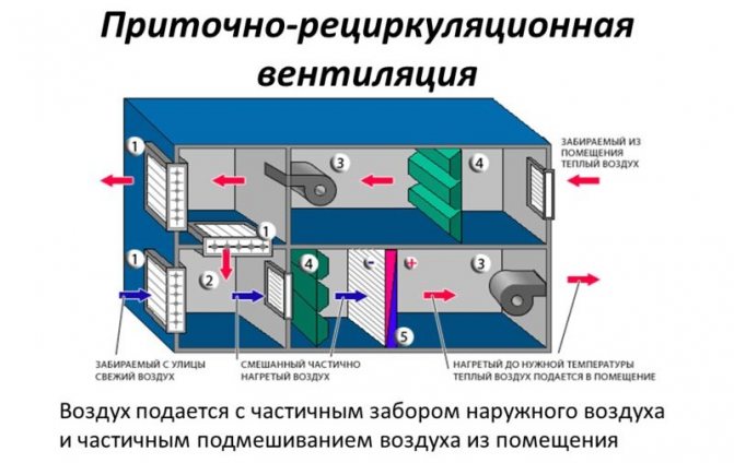
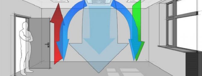
Scheme of recirculation forced ventilation.
The difference between external and internal conditions is determined taking into account the climate zone. On average, when turned on, the heater provides air heating of up to 40 °C to compensate for the difference between the warm internal and external cold flow.
To calculate the equipment required for room ventilation, you must use the following formula:
I = P / U, where:
- I is the number for the maximum current consumed by the equipment;
- P – power of the device required for the premises;
- U – voltage for powering the heater.
If the load is less than required, then you need to choose a device that is not so powerful. The temperature to which the air heater can heat the air is calculated using the following formula:
ΔT = 2.98 * P / L, where:

Table of comparative characteristics of natural and forced ventilation.
- ΔT – the number of air temperature differences observed at the inlet and outlet of the air conditioning system;
- P – device power;
- L is the value of equipment productivity.
In a residential area (for apartments and private houses), the heater can have a power of 1-5 kW, but for offices the value is taken to be higher - it is 5-50 kW. In some cases, electric heaters are not used; the equipment is connected to water heating, which saves energy.