Efficiency of using air heaters instead of heating radiators
The coolant circulating through water heating radiators transfers thermal energy to the surrounding air through thermal radiation, as well as through the upward movement of convection flows of heated air and the entry of cooled air from below.
The heater, in addition to these two passive methods of transferring thermal energy, drives air through a system of heated elements with a much larger area and intensively transfers heat to them. Assessing the efficiency of heaters and fans allows for a simple calculation of the cost of installed equipment for the same tasks.
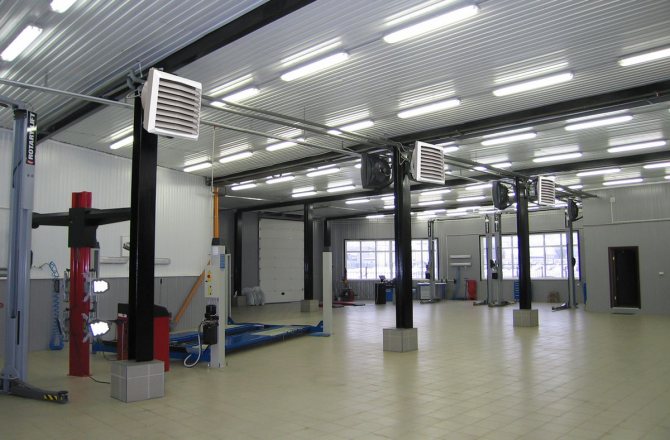
An example of heating a vehicle maintenance service room with air heaters.
For example, it is necessary to compare the cost of radiators and heaters for heating the showroom of a car dealership, taking into account compliance with SNIP standards.
The heating main is the same, the coolant is the same temperature, piping and installation can be ignored in a simplified calculation of the costs of the main equipment. For a simple calculation, we take the known norm of 1 kW per 10 m2 of heated area. A hall with an area of 50x20 = 1000 m2 requires a minimum of 1000/10 = 100 kW. Taking into account a margin of 15%, the calculated minimum required heating capacity of heating equipment is 115 kW.
When using radiators . We take one of the most common bimetallic radiators Rifar Base 500 x10 (10 sections), one such panel produces 2.04 kW. The minimum required number of radiators will be 115/2.04 = 57 pcs. It’s immediately worth considering that placing 57 radiators in such a room is unreasonable and practically impossible. If the price of a device for 10 sections is 7,000 rubles, the cost of purchasing radiators will be 57 * 7000 = 399,000 rubles .
When heating with air heaters . To heat a rectangular area in order to distribute heat evenly, we select from 5 Ballu BHP-W3-20-S water heaters with a capacity of 3200 m3/hour each with a similar total power: 25 * 5 = 125 kW. Equipment costs will be 22900*5 = 114,500 rubles .
The initial cost of heaters is almost 4 times less than the purchase of efficient bimetallic radiators.
When comparing the installed capacities of radiators and heaters by price, it is necessary to take into account in the calculation that one of the main indicators of standard heaters is the productivity of warm air. With a ceiling height of 6 meters in our example, the volume of the exhibition hall will be 1000 * 6 = 6,000 m3. Five air heaters with a capacity of 3200 m3/hour will refresh the air in the hall almost three times per hour, which will ensure its normal quality for workers and visitors not only in temperature, but also in composition.
The main area of application of air heaters is the organization of heating of rooms with large spaces for air movement:
- production workshops, hangars, warehouses;
- gyms, exhibition pavilions, shopping centers;
- agricultural farms, greenhouses.
Compact devices that allow you to quickly heat air from 70°C to 100°C, easily integrated into the overall automatic heating control system, are advisable to use in buildings with reliable access to coolant (water, steam, electricity).
The advantages of water heaters are:
- High profitability of use (low cost of equipment, high heat transfer, ease and low cost of installation, minimal operating costs).
- Fast air heating, ease of change and localization of heat flow (thermal curtains and oases).
- Reliable design, ease of automation and modern design.
- Safe to use even in high-risk buildings.
- Extremely compact dimensions with high heating output.
The disadvantages of these devices are related to the properties of the coolant:
- At temperatures below zero, the heater is easy to freeze. If water is not drained from the pipes in time, they can break if disconnected from the main line.
- When using water with a large amount of impurities, the device can also be damaged, so using it at home without filters and connecting it to a central system is impractical.
- It is worth noting that air heaters dry out the air greatly. When used, for example, in a showroom, humidifying climate control technology is required.
Air heating: air heater
Currently, stove devices are used that make it possible to heat the entire building from a single center, in which the air is heated, distributed within the building through channels. This heating system, called air heating, occupies an intermediate position between central water heating and local stove heating.
Air heating can be effective in cases where there is no central heating system in the cottage community or if the boiler room is located at a considerable distance from the house.
Air heating furnaces are technically more advanced and more economical than traditional storage furnaces.
Furnaces that produce heat to heat air currents circulating through their surface are called heaters. Their heating capacity is 6…30 kW. Heaters are large furnaces with a well-developed heat-transfer surface. Compared to conventional heat-intensive stoves, air heaters have the following advantages:
- saving labor costs during maintenance;
- rapid heating of the room;
- low capital costs for system installation;
- low metal consumption;
- high hygiene;
- the ability to regulate fuel consumption;
- reduced capital investment.
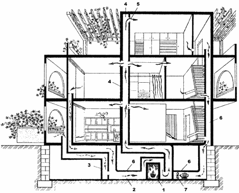
Rice.
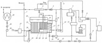
1. Installation diagram of a furnace-heater for an air heating system at home: 1 - heater; 2,4, 6 — channels; 5 - grate; 7 - fan. The essence of air heating using heater stoves is as follows:
- a heater is installed in the basement or technical underground of the building - a brick stove, the heating capacity of which is sufficient to heat the building as a whole;
- the air, washing the heating surfaces of the air heater, heats up and enters the heated rooms through the supply channel through the adjustable distribution grilles;
- Having given up some of the heat, the air returns through the return channel to the heater, where it is again heated.
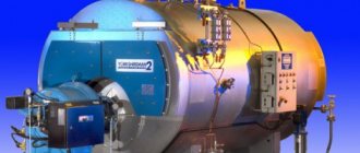
Rice.
2. Heater furnace, general view. The air circulation in the heater is called recirculation, and the air flow is called recirculation.
In the event that there are no people in the premises, the building can be heated in full recirculation mode, i.e. without outside air intake. This mode is economical in terms of heat consumption. During periods when residents are in the house, according to sanitary standards, a certain amount of outside air must enter the building. For this purpose, an air intake channel is used, through which outside air is directed to the heater, mixing in the channel with the recirculation medium. The amount of outside air is regulated by a damper installed in the duct.
Rice. 3. Stove-heater, section: 1 - firebox; 2 - channel; 3 - pass; 4 — heater; 5 — brick nozzle; 6 - chimney; 7 — view; 8 - channel; 9 — tuck; 10 - collector.
The movement of coolant through the channels of an air heating system can occur due to gravitational forces acting due to the difference in the density of warm and cold air. When using gravitational forces as circulation incentives, the distance from the heater to the underground channel for one-story buildings should not exceed 6 m. The use of fans greatly increases the radius of the air heating system (50 m or more).
The required power of the fan motor N (W) is determined by the formula:
N = 0.287*10-6LP/ηв where, L is the volume of circulating air, m3/h; P is the pressure developed by the fans, Pa; ηv — fan efficiency.
Functional diagram of the heater furnace:
- the fuel is burned in the firebox, from where the combustion products pass through the channel and pass to the heater containing a heat-storing nozzle;
- having given up their heat, the combustion products are collected in the manifold and, going around the underpass, are directed into the lifting channel, which is blocked by the view;
- the chimney is erected on the walls of the channel.
Rice.
4. Connection of the heater with the firebox. The laying of the heater must be carried out very carefully by highly qualified stove workers. During the laying process, it is taken into account that the mass of the firebox, heater nozzle and chimney are different, so the settlement of these elements occurs differently. As a result, it is not allowed to tie the firebox, heater and pipe together. Sedimentary seams are left between these elements. The exception is the small areas where the firebox connects to the heater and the heater to the pipe. The heater attachment is made of carefully selected bricks laid on edge.
Rice. 5. Heater nozzle.
The outer walls of the heater are plastered, achieving gas-tight enclosures.
Sometimes internal channels are made with a metal coating, which significantly increases the tightness of the structure.
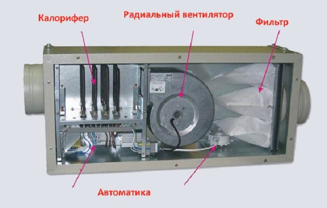
Device and principle of operation
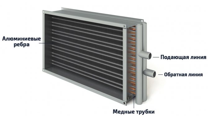
The design of the main element of the heater - the heat exchanger.
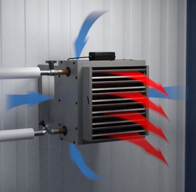
The heater is capable of raising the temperature of the air flow passing through it by 110 degrees using incoming air of negative temperature (up to -25°C). The connection of such devices to the heat supply source occurs before the collector of the internal heating networks, so as not to reduce the temperature of the system coolant. Electric and steam heaters are connected in parallel, and water heaters are connected in series.
The operating principle of a water heater is as follows:
- Water from the heating main with a temperature from +80°C to 180°C enters a block of thermal elements located horizontally. Each thermal element is a steel, aluminum, bimetallic or copper tube.
- The tubes heat the air inside the device.
- A fan built into the unit takes air from the room or from the street and blows it through the thermal elements, ensuring the movement of hot air into the room.
Types of heaters
There are several types of air heaters used in different areas and conditions.
Let's take a closer look at them:
Mermen
The most common group of devices, characterized by high efficiency, safety and ease of operation. They use hot water as a coolant, coming from the central heating network, hot water supply or from their own boiler. A water heater for fresh air ventilation is the most convenient and economical solution, allowing you to perform the assigned tasks with minimal maintenance or repair costs. The only drawback of the device is the need to connect to the coolant supply system, which creates certain difficulties at the installation stage and prevents quick transfer to another location.
Steam
Steam devices are complete analogues of water devices and in practice differ from them only in the type of coolant. The only difference between steam devices is the greater thickness of the tube walls - 2 mm versus 1.5 for water ones. This is due to the high pressure in the system, requiring reinforced channels for circulation. Otherwise, the devices are identical and have the same operating rules and requirements.
Electrical
An electric heater for supply ventilation does not require a coolant supply, since the heating source is electric current. Connecting such devices is much simpler, which makes them mobile and easy to use, but high energy costs limit the use of this group. Most often, they are installed for local heating when performing one-time work, and are used as emergency or temporary heat sources.
The need to calculate the heater
Equipment for air heating of premises requires proper selection. Matching the power and performance of the devices to the parameters of the building, climatic conditions or the needs of people are the most important aspects of the operation of air heaters. If the installed device does not meet the needs of the premises and does not cope with its functions, then a feeling of discomfort will appear, the performance of personnel will decrease, and production conditions will worsen, which may negatively affect the quality of products, services provided, or other areas of human activity.
READ MORE: Calculator for calculating the roof area of a hip or hip roof - with diagrams and explanations
Expert opinionHeat supply and ventilation engineer RSV Fedorov Maxim Olegovich
Important! It should immediately be noted that performing such a calculation is a complex task that requires considerable experience and knowledge. For an unprepared person, such a task will most likely be overwhelming and will require turning to specialists
If you don’t have confidence in your abilities, then it’s better not to waste time and immediately order a calculation from a specialized organization that employs competent specialists.
Selecting a device type
Before you start choosing the type of device, you need to find out what kind of air heaters exist. They can be:
- electric
- water
- gas
Water heater calculation
Calculation of the heater power required to heat a particular room is carried out taking into account such data as:
- The volume (mass) of supply air that needs to be heated.
- Initial (external) temperature of air masses.
- The target temperature to which the air must be heated before being supplied to the room.
- Temperature regime of the coolant.
The heater is calculated based on the heating surface area and the required power. Each operation has its own formula. The heater power can be calculated only taking into account real data in specific conditions, among which the most important are:
- connection method (to the central heating network or boiler room);
- strapping method.
Calculation of heater power
Qt – heater heat power, W; L – air flow, m³/hour ρair – air density. The density of dry air at 15 °C at sea level is 1.225 kg/m³; air – specific heat capacity of air equal to 1 kJ/(kg∙K)=0.24 kcal/(kg∙°С); tin – air temperature at the outlet of the heater, °C; tnar – outside air temperature, °C (air temperature of the coldest five-day period with a probability of 0.92 according to SP 131.13330.2012)
Heater power calculator
Air flow, m³/hour: Air density, kg/m³: Specific heat capacity of air, kJ/(kg × K): Air temperature at the air heater outlet, °C: Outside air temperature, °C:
Coolant flow for the heater G - water flow for heat supply to the heater, kg/h; 3.6 - conversion factor W to kJ/h (to obtain flow rate in kg/h); Qt – heater heat power, W; sv – specific heat capacity of water equal to 4.187 kJ/(kg∙K)=1 kcal/(kg∙°C); tpr – coolant temperature (straight line), °C; trev – coolant temperature (return line), °C.
Coolant flow calculator for heater
Thermal power of the air heater, W: Specific heat capacity, kJ/(kg × K): Coolant temperature (forward line), °C: Coolant temperature (return line), °C:
Air heating process diagram
You can determine the required heater power using special diagrams. The amount of energy required (Joules) to heat 1 kilogram of air is produced using the i-d diagram of moist air. The calculation is made under the condition that the air heating process occurs at d = const (with constant moisture content). Next, taking into account the calculated air flow rate and the conversion of units (J/s to kW), the heater power is determined. i–d diagram of humid air
To obtain accurate data, you can use online calculators, with which you can find out the power indicator by indicating performance and temperature. Since the performance of the installation may decrease as a result of gradual wear, it is recommended to include a power reserve of 5 to 15% in the calculation.
Automatic and manual temperature control
Skip to content
This page provides an online calculation of water heaters. The following data can be calculated online:- 1.
required heater power for the heating and supply unit, depending on the volume and temperature of the heated air - 2.
air temperature at the outlet of the water heater, depending on its power, volume and temperature of the forced air— 3. hot water flow, depending on the selected power of the heater and the coolant schedule used
1. Online calculation of water heater power (heat consumption for heating supply air)
The following indicators are entered into the fields: the volume of cold air pumped by the fan (m3/hour), the temperature of the air entering the heater (as a rule, the average temperature of the coldest five-day period in your region is taken), the required temperature at the outlet of the heater. The output (based on online calculation results) shows the required power of the water heater to comply with the specified conditions.
1 field. The volume of supply air passing through the heater (m3/hour)2 field. Air temperature at the inlet to the water heater (°C
READ MORE: Calculation of gas boiler power
3 field. Required air temperature at the outlet of the heater
(°C) field (result). Required heater power (heat consumption for heating supply air) for the entered data
Online selection of a water heater based on the volume of heated air and thermal power
Below is a table with the range of water heaters produced by our company. Using the table, you can roughly select an air heater suitable for your data.
Initially, focusing on the air heating volume per hour (air output), you can select a water heater for the most common thermal conditions.
By clicking on the name of the selected air heater, you can go to a page with detailed thermal parameters and working calculations for this water heater.
| Heater name | Air capacity range, m³/h | Temperature of incoming/outgoing air, °C | Thermal power range (depending on air output), kW |
2. Online calculation of the air temperature at the outlet of the water heater
The following indicators are entered into the fields: the volume of heated air (m3/hour), the air temperature at the inlet to the heater, the power of the selected air heater. At the output (based on the results of online calculation) the temperature of the heated air leaving is shown.
3 field. Thermal power of the selected air heater
(kW) field (result). Air temperature at the outlet of the heater (°C)
3. Online calculation of coolant consumption by the heater (depending on the temperature curve and power)
The following indicators are entered into the fields: the power of the selected heater (kW), the temperature of the incoming coolant (forward flow), the temperature of the coolant at the outlet of the heater (return). The output (based on online calculation results) shows the required amount of coolant per hour to comply with the specified conditions.
1 field. Heat performance (power) of a water heater (kW)2 field. Coolant temperature at the air heater supply (°C)
3 field. Coolant temperature at the outlet of the air heater
(°C) field (result). Heater coolant consumption at a given temperature graph (kg/hour)
The air temperature in the cabin is regulated using mixing valves that change the temperature of the air supplied to the cabin within the range of 0 - 110 ° C. The mixing valve control switches are located on the cockpit panel. A switch for switching the valve control to “Automatic” and “Manual” and two “Heat-Cold” switches can be installed on the panel » regulation of the temperature of the air supplied to the cabin by the left and right manual control systems. On the same panel there is a handle for setting the air temperature and a thermometer.
The temperature of the air supplied to the cabin, in this case, is controlled by a two-pointer electric thermometer installed on the dashboard panel; the air temperature sensors are installed in the SCR pipelines.
A control unit and a thermal relay can also be turned on, limiting the air temperature in the pressurized cabin during both automatic and manual air temperature control.
The SCV supplies fresh air to the corresponding zone of the pressurized cabin and automatically maintains the temperature set on the control panel.
So, for example, in the summer, when the outside air temperature on the ground is 45 ºС, the air conditioning system can cool the pressurized cabin zones in flight to a temperature not higher than 25 degrees.
In winter, when the outside air temperature on the ground is -50 ºС, the air conditioning system can heat the pressurized cabin zones to a temperature not lower than 17 degrees.
With manual control, the temperature of the supplied air will not exceed 100 ºС. This is monitored by a thermal relay in the system. If, in the event of a failure of the control unit, the temperature of the air supplied to one of the cabin zones exceeds 120 ºС for a period of more than 20 s, then the air supply to the corresponding subsystem will be automatically stopped by a signal from the thermal relay. At the same time, the damper will open, connecting the subsystems of the front and rear zones of the cabin, and the operating subsystem will supply air to the interior zones.
It is also possible to supply air to individual zones. In the individual ventilation subsystem, the air temperature is automatically maintained at 18 ºС, in the intensive cooling mode - 13 ºС. With manual control, the temperature will not exceed 50 ºС. This is monitored by a thermal relay in the subsystem.
On the ground, when the engines are not running, air into the air conditioning system can be drawn from the auxiliary power unit. Before passengers board the aircraft, through the ground air conditioning fittings, at an outside air temperature above 25 ºC, cooling is carried out, and below 5 ºC, the passenger compartment and crew cabin are heated; at a temperature of 5-25 ºC, the passenger compartment and cockpit are ventilated.
READ MORE: SanPiN 2.2.4.548-96 “Hygienic requirements for the microclimate of industrial premises. Sanitary rules and regulations"
Brief overview of modern models
To get an impression of the brands and models of water heaters, let’s look at several devices from different manufacturers.
No. 1 – KSK air heaters
Heaters KSK-3, produced at the company T.S.T.
The model range of domestically produced KSK water heaters includes 2/3/4-row devices that differ in performance and size
Specifications:
- coolant temperature at the inlet (outlet) – +150 °C (+70 °C);
- inlet air temperature – from -20 °C;
- working pressure – 1.2 MPa;
- maximum temperature – +190 °C;
- service life – 11 years;
- working resource – 13,200 hours.
Air resistance calculation
10. Calculation of aerodynamic drag. The amount of air losses can be determined in two ways. The first is to calculate using a formula using the coefficient and degree values of the selected heater. The second is by selection - according to the table, using data at different mass air speeds. View tables with data on the aerodynamic resistance of KPSk steam heaters.
| Estimated values for calculating aerodynamic drag | ||||||||
| KPSk2 (double-row) | B | r | KPSk3 (three-row) | B | r | KPSk4 (four-row) | B | r |
| 4.23 | 1.832 | 6.05 | 1.832 | 8.63 | 1.833 | |||
ΔPa (Pa) = B • Vr V – actual mass air velocity, kg/m²•s; B, r - the value of the module and degrees from the table.
An example of calculation and selection of a KPSk heater. Step-10
Select a suitable KPSk heater for heating 6500 m³/hour from a temperature of -28°C to +29°C. The coolant is dry saturated steam with a pressure of 0.1 MPa. 10. The task is to find out the aerodynamic resistance of the selected heaters when working under given conditions. ΔPa (Pa) = 4.23 • 4.011.832 = 53.8 Pa - for heater KSk 2-11 ΔPa (Pa) = 6.05 • 4.011.832 = 77.02 Pa - for heater KSk 3-11 ΔPa (Pa) = 8.63 • 4.011.833 = 110.03 Pa - for heater KSk 4-11 4.01 - actual mass air velocity in the frontal section, kg/m²•s; 4.23, 1.832 (6.05, 1.832; 8.63, 1.833) - the value of the module and degree from the table depending on the row of the steam air heater.
When installing steam heaters sequentially along the direction of air movement, the resulting aerodynamic resistance value is multiplied by the number of rows of heat exchangers.
Water heaters for fresh air ventilation
All available types of heating devices for ventilation are inferior or, at best, are similar in their technical characteristics to water-based devices.
The main area of use of air heaters is buildings or premises in which, for various reasons, it is not possible to install radiators. For example, with large volumes of rooms, radiators simply cannot cope; on the contrary, it will be the most effective. The most rational location of water heaters is the supply ventilation line, since it is not practical to heat the exhaust flow.
heating of the supply jet is actively , used to preserve the existing heat in the room. If a fresh stream is transported through a long line of air ducts, then condensation will accumulate on them without heating the air, which will create a lot of operational problems. To solve all these issues, water air heaters are used.
Water air heater: operating principle and design
The most common type are. They replaced plate structures, which were less easy to maintain and required periodic maintenance in a rather labor-intensive manner.
- View cart Add to cart / Details
Heater KSK 4-1
8 100 ₽PostponePostpone ⚖ Compare
- View cart Details
- View cart Details
- View cart Add to cart / Details
Heater KSK 4-2
9,300 ₽PostponePostpone ⚖ Compare
Heater KSK 4-3
10 550 ₽PostponePostpone ⚖ Compare
Heater KSK 4-4
11,770 ₽PostponePostpone ⚖ Compare
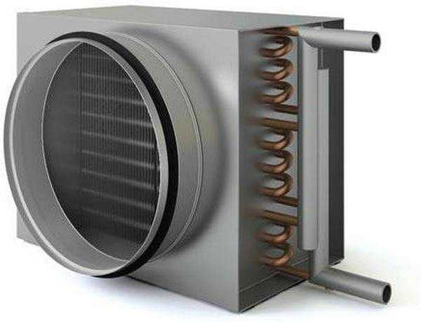
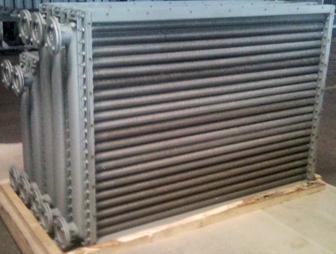
Heater
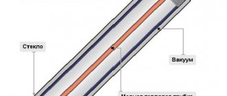
The main element of the heater is a steel tube , the outer surface of which is coated with aluminum fins. These fins serve as a heat-transfer surface, the total area of which is quite large. At the same time, the total outer diameter of the tubes (including fins) is 37 mm, and the tube itself is 16 mm, so the depth of the fins is relatively small and does not pose the risk of filling with dirt, dust or other foreign materials that reduce heat transfer. The distance between the fins is 2.8 mm, which allows you to retain heat even with intense airflow, making the device highly efficient.
Tubes
The tubes are installed in a flat rectangular frame in 2, 3 or 4 rows. The distance between the axes of the tubes promotes maximum heat transfer from their surface. The air flow is supplied using an axial or radial fan, it depends on the installation location of the device and the specifics of its operation.
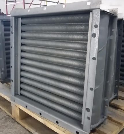
Installation
To install the heater, the housing (frame) has several oblong mounting holes on flange mounts . With their help, devices can be installed in a system of air ducts, in openings or other supporting structures. Sometimes a separate installation is used when the device serves a room of a certain size and is not built into the overall heating or ventilation system.
Calorifiers (heat exchangers) description, types and advantages
The content of the article:
Description and use of heaters Varieties (types) of heaters Advantages of using a heater
Description and application of air heaters
A duct heater (an alternative name is a heater) is a device designed for heating premises by heating the supply air. The operating principle of the device is based on heating the air as it passes through a heat exchanger . In this case, the temperature of the incoming air flow increases due to the transfer of thermal energy from the coolant.
In practice, duct heaters are used as part of air heating , ventilation and air conditioning systems in industrial and utility premises. The most common objects of application are production workshops, hangars, warehouses for workpieces, equipment and finished products. In addition to direct heating functions, an example of the practical use of air heaters is their work as part of drying installations. The heating elements are fed by coolant, which enters the device through connection to centralized heating networks, water supply or electricity supply.
Varieties (types) of heaters
Duct heaters differ in two main indicators - the geometric shape of the body and the type of coolant used. Based on the body geometry, products in this category are divided into rectangular, round and square.
To heat the supply air flow, the devices use three types of coolants - water, steam and electricity. The heat exchangers themselves are classified depending on the type used .
Water heaters
The most common type of heat exchangers are KSk air heaters . The abbreviation KSk stands for “spiral-rolled heater”. The structural design of this type of product involves a tubular structure fixed in a sheet metal housing. The location of the pipes is across the direction of air flow. Depending on the required performance, models in the category are divided into heat exchangers with two, three and four rows of heaters. The latter are played by composite elements - steel tubes with aluminum fins applied to their outer surface.
Water circulates through the pipes from the bottom row to the top, which prevents airing in the pipeline. At the ends of the housing there are connecting flanges, the location of the holes in which corresponds to the connecting dimensions of the ventilation ducts .
Electric heaters
An electric-type duct heater involves heating the air using metal heating elements installed transverse to the flow direction, finned using incandescent filaments or spirally wound wire. Depending on the model, the number of heating elements in an electric heater varies from one to four.
The air pumped by the fan is forced onto the heating elements, which heat up under the influence of the voltage supplied from the mains. As a result, heated air flow is directed into the room, which ensures that a comfortable temperature is maintained. The required heating level is controlled and ensured using special temperature sensors that are installed indoors.
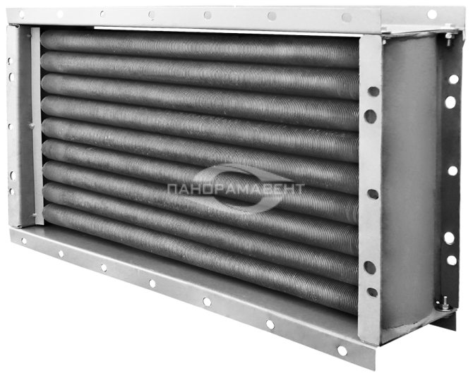
Steam heaters
This type of heat exchanger is designated by the abbreviation KPSk, which stands for “spiral-rolled steam heater.” KPSk heaters are similar in design and parameters to water heat exchangers. They also include a sheet metal body, end connection flanges and heating tubes.
The only difference is that in steam duct heaters, instead of water, hot water steam is supplied through the pipes, the temperature of which is +190 °C. The device is connected to a centralized steam supply system using inlet and outlet pipes, which are located on one of the sides of the housing.
Advantages of using a heater
Modern models of air heaters have many advantages over traditional methods of heating rooms. The list of advantageous characteristics includes the following factors:
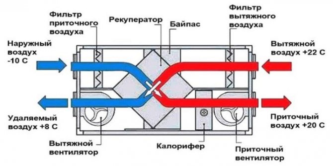
- Economical consumption of coolant due to thermal energy recovery. Devices operating on the principle of heat recovery are responsible for controlling the incoming and outgoing air flow. In this case, the outgoing exhaust air flow transfers the accumulated thermal energy to the heat exchanger , which allows minimizing the consumption of coolant from the outside.
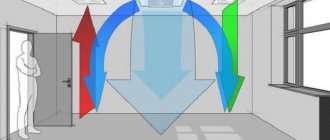
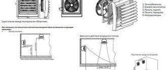
- Possibility of uniform heating of the internal volume of the room. Heaters are installed under the ceiling to eliminate the influence of air flows on the operation of equipment and personnel. The air is directed downwards using adjustable ventilation grilles installed at the end of the heaters . This allows you to balance the temperature in all points of the room.
- Possibility of automatic temperature control. heating on and off . This eliminates the possibility of equipment overheating and ensures that a comfortable room temperature is maintained.
- High performance heating elements. The fins of the heating elements provide an increased contact area of the heater with the passing air, which contributes to the rapid heating of the incoming flow.
In addition to this, it is worth noting that heaters have an increased safety and performance life, and are also easy to maintain and repair.
Heaters KSk and KPSk – size range
| Model range of 3/4 row heat exchangers | |||
| Water heaters KSK 3 three-pipe | Water heaters KSK 4 four-pipe | Steam heaters KPSK 3 three-pipe | Steam heaters KPSK 4 four-pipe |
| KSk 3-1 | KSk 4-1 | KPSk 3-1 | KPSk 4-1 |
| KSk 3-2 | KSk 4-2 | KPSk 3-2 | KPSk 4-2 |
| KSk 3-3 | KSk 4-3 | KPSk 3-3 | KPSk 4-3 |
| KSk 3-4 | KSk 4-4 | KPSk 3-4 | KPSk 4-4 |
| KSk 3-5 | KSk 4-5 | KPSk 3-5 | KPSk 4-5 |
| KSk 3-6 | KSk 4-6 | KPSk 3-6 | KPSk 4-6 |
| KSk 3-7 | KSk 4-7 | KPSk 3-7 | KPSk 4-7 |
| KSk 3-8 | KSk 4-8 | KPSk 3-8 | KPSk 4-8 |
| KSk 3-9 | KSk 4-9 | KPSk 3-9 | KPSk 4-9 |
| KSk 3-10 | KSk 4-10 | KPSk 3-10 | KPSk 4-10 |
| KSk 3-11 | KSk 4-11 | KPSk 3-11 | KPSk 4-11 |
| KSk 3-12 | KSk 4-12 | KPSk 3-12 | KPSk 4-12 |
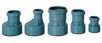
Differences in air heaters by tube type
Heating heaters may differ in the type of tubes used to transfer heat. The following models of such devices are distinguished:
Attention ! Caloriferous smooth-tube heating is the least efficient, but the cost of such products is noticeably lower.
Differences in air heaters by installation method
Household and industrial air heaters can have the following placement options:
- Wall.
- Ceiling.
- Floor.
Some models can also be built into a forced ventilation system, which allows you to maximize the efficiency of this heating method.
Connection diagram and control
Electric heaters must be connected in compliance with all safety requirements. The connection diagram for the electric heater is as follows: when you press the “Start” button, the engine starts and the heater ventilation is turned on. At the same time, the engine is equipped with a thermal relay, which, if there is a problem with the fan, instantly opens the circuit and turns off the electric heater. It is possible to turn on the heating elements separately from the fan by closing the blocking contacts. To ensure rapid heating, all heating elements are turned on simultaneously.
To increase the safety of the electric heater, the connection diagram includes an emergency indicator and a device that prevents the heating elements from turning on when the fan is turned off. In addition, experts recommend including automatic fuses in the circuit, which should be placed in the circuit together with the heating elements. But installing automatic machines on fans, on the contrary, is not recommended. The heater is controlled from a special cabinet located near the device. Moreover, the closer it is located, the smaller the cross-section of the wire connecting them can be.
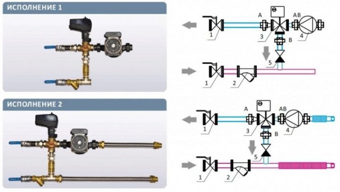
When choosing a water heater connection diagram, you need to focus on the placement of mixing units and units with automation. So, if these units are located to the left of the air valve, then a left-hand design is implied, and vice versa. For each version, the location of the connecting pipes corresponds to the air intake side with the installed valve.
There are a number of differences between left and right placement. So, with the right-hand version, the water supply tube is located at the bottom, and the “return” tube is located at the top. In left-sided circuits, the supply pipe enters from the top, and the outflow pipe is located at the bottom.
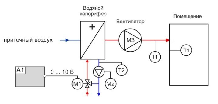
When installing a heater, it is necessary to install a piping unit necessary to monitor the performance of the device and protect it from freezing. Piping nodes are the reinforcement frames that regulate the flow of hot water into the heat exchanger. Piping of water heaters is done using two- or three-way valves, the choice of which depends on the type of heating system. Thus, in circuits heated by a gas boiler, it is recommended to install a three-pass model, while for systems with central heating, a two-pass model is sufficient.
Controlling a water heater involves regulating the thermal power of heating devices. This is made possible by the process of mixing hot and cold water, which is carried out using a three-way valve. When the temperature rises above a set value, the valve releases a small portion of cooled liquid into the heat exchanger, which is taken at the outlet.
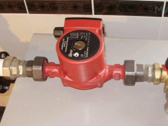
To increase the efficiency of the system, it is recommended to include a circulation pump in the connection diagram. The device is installed at the outlet of the heat exchanger, which allows it to work with already cooled glycol solution or water.
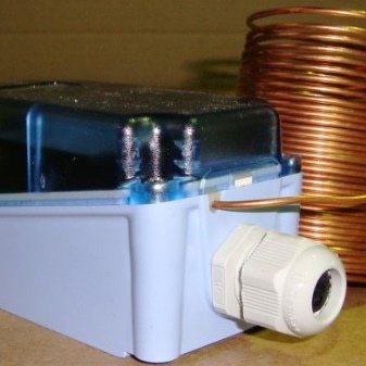
In addition, the installation diagram of water heaters does not provide for the vertical arrangement of inlet and outlet pipes, as well as the location of the air intake at the top. Such requirements are due to the risk of snow getting into the air duct and melt water flowing into the automation. An important element of the connection diagram is the temperature sensor. To obtain correct readings, the sensor must be placed inside the air duct in the blowing section, and the length of the flat section must be at least 50 cm.
Ventportal
The water heater in the supply ventilation itself is a fairly reliable device and does not require frequent maintenance. But the quality of its work depends entirely on the automation system.
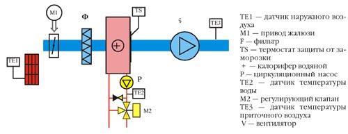
Let's take a closer look at the installation drawing.
Supply ventilation works as follows: outside air enters through the air intake grille and, passing through the louvered grille, enters the filter section, where mechanical impurities and dust are removed. The purified air is then sent to a water heater, in which it is heated using the heat of hot water from the network mains. The air then enters the fan section, from which it is transported into the supply duct.
The connection of the heater, or rather the control valves, depending on the source of hot water, can be done in two ways:
a) when consumed from the city network, where the return water flow is not fixed and there is only a need to maintain the return water temperature, a two-way valve is used,
b) when consumed from a local boiler room or boiler, where the return water flow is strictly fixed and changes in it can affect the functioning of the network, a three-way valve is used.
The operation of the system in both the first and second cases is practically no different. The difference is that in the version with a two-way valve, it is possible to completely stop the flow in the return line. This cannot but affect the coolant savings, but for the purposes of this article we will consider the first and second methods equivalent.
Let's consider what functions the automation system should perform in this air preparation process:
- turning on/off the system (manually or by timer);
- maintaining the required air temperature in the supply channel with the fan turned on in operating mode;
- heater protection from defrosting;
- maintaining the return water temperature when the fan is turned off in standby mode;
- training start of the pump.
Let's divide the automation process into three modes:
- pre-launch warm-up;
- launch;
- Job;
- standby mode.
Before moving on to describing the operation of the automation system in these modes, it is necessary to consider two tasks: what we will regulate and with what parameters we will carry out the analysis.
Let's return once again to the installation diagram.
“Outdoor air sensor” is a sensor installed outdoors that indicates the ambient temperature.
“Air temperature sensor in the duct” is a sensor installed after the fan section on a straight section of the air duct, which determines the temperature in the duct.
“Return water temperature sensor” is a sensor installed immediately after the water heater on the pipe, indicating the water temperature. Note that for more accurate regulation, this sensor should be located as close as possible to the outlet of the heater, since in some systems, at low water flow rates in the circuit, strong inertia is possible.
In general, for greater controllability and dynamism, it is desirable that the water circuit of the heater piping be extremely short. For more reliable protection against freezing of the working substance during winter operation, a “freeze protection thermostat” is installed after the heater. It is attached to the heat exchange surface of the heater and is triggered when there is a significant decrease in temperature or zonal overcooling of the heater.
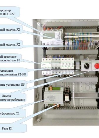
An important role in the control of the installation is played by the automation system, which includes a programmable controller, intermediate relays, starters and actuators.
As for the actuators, there can be any number of them. The main ones are: louvre drive, fan contactor, pump starter and adjustable valve. As a rule, if there are no requirements for the rigid operation of the louvre grille (impossibility of operating under vacuum), then its drive and fan contactor are combined into single groups. The signal to turn the fan on/off is transmitted simultaneously with the signal to open the louver grille.
Before starting the system in winter, a pre-start warm-up is performed. At the first moment of time, when the system has not yet started (standby mode), the water control function in the return line is supported. To maintain this function, the valve is almost closed and opening the throttle valve and starting the fan during this period threatens to defrost the heater.
Therefore, an important task during warm-up is to monitor the return water temperature sensor in order to avoid a sharp drop in the air supply temperature. Warming up is also necessary so that at the time of start-up, already heated air is supplied to the air duct to create comfortable conditions in the room.
Warming up can be carried out both over time and upon reaching a certain return water temperature. In our opinion, the optimal solution is to heat the water to a given temperature, and the heating should end within a certain time interval. For the heater piping system, this means that the circulation pump is turned on and the three-way valve is working.
After the system is warmed up, it starts and enters the mode. At this time, it is very important to control the return water temperature, as it can begin to drop sharply, both due to low outside air temperatures and due to a decrease in circulation flow.
At the time of startup, it is also important to monitor the temperature in the duct. Therefore, we believe that the startup process should represent a curve for achieving the set temperature in the channel, based on the readings of two sensors: the return water sensor and the temperature sensor in the channel. Moreover, preference in control is given to the return water temperature, since the safety of the heater when switched on in winter depends on it.
Thus, at different times, depending on the sensor readings, the adjustable parameter can be both the return water and the temperature in the channel. As can be seen at the initial point in time (start-up), we control the temperature of the return water. What to do if it falls steadily? It would seem that it is necessary to turn off the system and then begin the startup procedure again.
We suggest not stopping the system, but briefly opening the valve to 100%. Thus, we solve two problems: we save the system from the restart process and the time it takes to enter the mode. If after this the temperature continues to drop, then the only solution is to stop the unit until the cause of the malfunction is determined.
After approaching the set temperature in the channel, the system enters operating mode.
When the supply ventilation is turned off, the system goes into standby mode. Its main functions are maintaining the return water temperature and protecting the heater from defrosting.
materials from the site were used - https://www.mir-klimata.com/archive/number04/article/article16/
Installation Tips
Heaters with sensors in the greenhouse maintain the desired temperature.
The water heater is installed in rooms connected to the central heating main. When installing yourself, you should follow the recommendations of specialists:
- The diagonal of the heater depends on the bending characteristics of the channels, the type of damper and structural elements.
- To protect the heater from freezing, installation is carried out in rooms with a temperature not lower than 0 degrees.
- Before installation, it is necessary to inspect the plates and tubes for integrity.
- Weld-on flanges are easiest to connect end-to-end.
- Direct-flow air vent valves are located at the top of the outlet and supply manifolds.
- The joints between the device and the ventilation system are sealed.
- Wall-mounted models are installed by fastening the console with two self-tapping screws.
If you have no experience connecting and tying the system, it is better to entrust the work to specialists.
Basic operating rules
Calorific water or electric heating is a fairly safe system, which, however, requires compliance with certain rules of use. Mandatory requirements
- Monitoring the composition of indoor air to ensure its compliance with GOST 12.1.005-88.
- Installation must be carried out strictly according to the manufacturer's instructions.
- Maintaining coolant temperature no more than 190 C and pressure up to 1.2 MPa (for water, steam devices).
- Inadmissibility of placement near sockets (for electric heaters).
- It is prohibited to hang clothes, shoes, or other items on the building to dry.
It is important to remember that water equipment cannot be installed in rooms with an initial temperature below zero degrees. Electric heating coils with a fan will not be able to perform their functions if the fan is turned off.