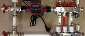
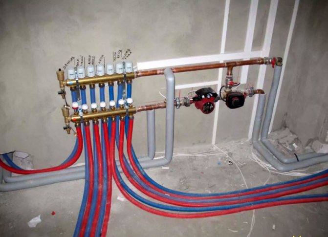
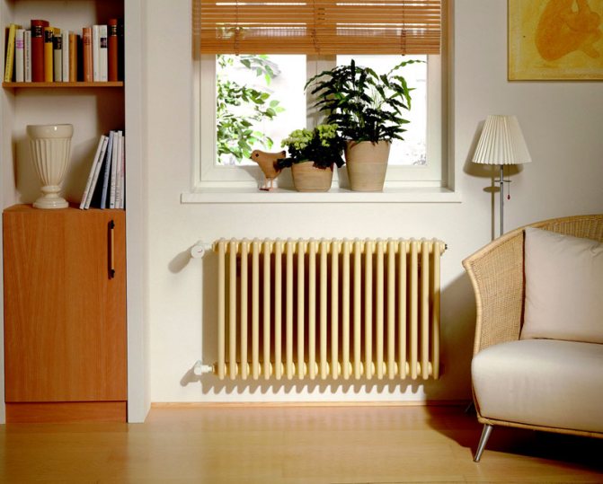
Comfortable living room temperature is the main task of heating. But not everyone realizes that in addition to the main components and units (boiler, radiators, circulation pump), less noticeable devices are also responsible for heat. One of them is a three-way valve for heating with a thermostat, the circuit of which is not complicated, but requires careful, detailed consideration. Such nodes are found today in every apartment or private house. In today's review, we will analyze the principle of operation, the device and what functions this element performs. Along the way, we will consider the installation nuances and the cost of various models on the Russian market.
Three-way valves are necessary for heating systems of private and apartment buildings
Why is it necessary to regulate heat flow in a heating system?
The design and installation of heating is carried out according to preliminary calculations, based on the quality of the thermal insulation of the home and the average temperature of the climatic zone. However, the weather does not obey human desires - the wind changes, the temperature outside the window “floats”. It is possible to change the insulation parameters of a building during operation. In this case they say that the best is the enemy of the good. Too high a room temperature does not add comfort. This is where the three-way control valve comes to the rescue, by means of which the intensity of the supply of hot coolant to the radiator is regulated.
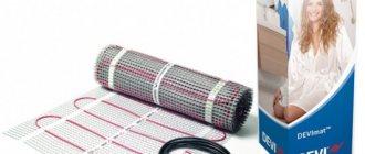
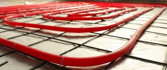
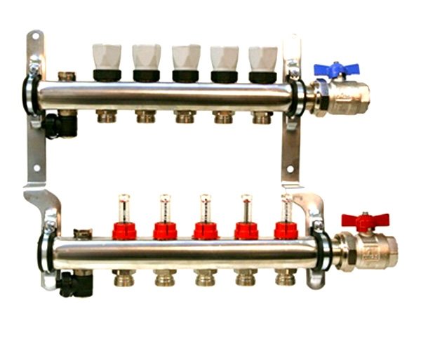
Three-way taps, working in tandem with sensors, will provide a comfortable temperature for the heated floor
Now we are talking about apartment buildings where the resident does not have access to the boiler to change the heating value of the coolant. In addition, because of one apartment, changing the temperature regime along the riser is, to say the least, illogical. In private houses there are fewer problems - the owner can reduce the supply of hot coolant or the amount of heating from the boiler, but here, too, not everything is so simple. Rooms on the leeward side cool down faster. And again there is only one way out - including a three-way separating or mixing valve in the circuit.
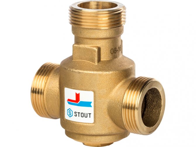
Such devices may have different appearances, but perform the same job.
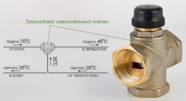
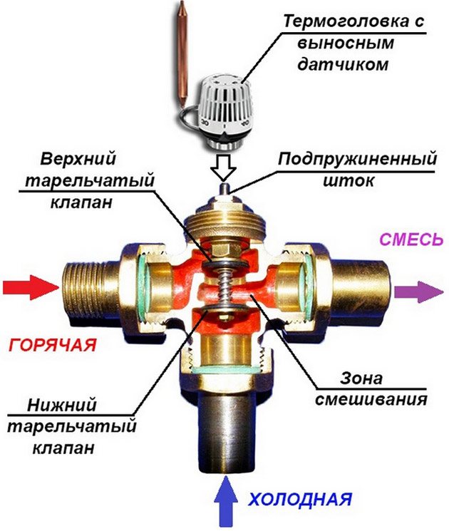
How does a thermostatic mixing valve work?
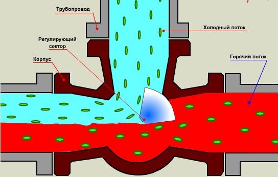
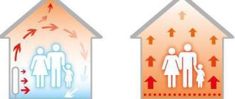
The essence of the device essentially boils down to mixing a hot flow with a warm one, thereby regulating the floor temperature. A three-way valve is installed to distribute the flow of working fluid into two circuits. The three-way design stem is always open. It is configured to regulate a certain volume of liquid. Due to this, it becomes possible to obtain a qualitative and quantitative volume of liquid in the desired size.
The three-way valve is capable of shutting off variable flow. Thanks to this, adjustment of flow and pressure becomes possible. A three-way valve equipped with an electric drive is much more functional. It is capable of automatically adjusting the temperature. It is these devices that are usually used when connecting underfloor heating.
Related article: Wallpaper for the kitchen and fashion trends 2020
Areas of application of limit valves with a thermostat
Such elements of heating shut-off valves are used not only for uniform supply of coolant to radiators. Three-way mixing valves for heated floors have become widespread. In this case, it becomes possible to adjust the heating depending on the temperature outside the window and drafts. This function is especially in demand when small children play indoors. Overheating the floor in this case can lead to decreased immunity and frequent colds.
Helpful information! Using a thermo-mixing valve for a “warm floor” will not only provide a comfortable temperature. Such a device will help save on fuel or electricity - the boiler does not need to heat the coolant, the temperature of which is already high.
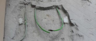
You can independently install a thermostat and control system on such a valve.
Motorized control valves
May 1, 2010
The complexity of engineering systems increases every year, the requirements for their energy efficiency, reliability, and safety are increasing, which dictates the use of modern pipeline fittings, primarily control ones.
In this article we will look at the main types of control valves that play an important role in solving the above problems, and also analyze some of the features of control valves supplied by the ADL Company with PS-Automation electric drives (Germany).
Direct-acting control pipeline valves, as is known, use the energy of the same medium to regulate the flow parameters of the working medium in a certain section of the technological system or pipeline. Due to this, the advantages of this type of valve are: independence from external energy sources, control accuracy, and reliability. However, there is also a drawback that often greatly complicates and limits the use of direct-acting regulators - the lack of flexibility. In other words, each controller is designed to be used within a very narrow range of system parameters. For example, if we are using a direct acting pressure regulator to regulate an output pressure of 5 bar, then to change the setting to, for example, 10 bar (all other parameters unchanged), we will most likely need a completely different valve.
The following types of direct acting regulators are available:
- pressure reducing valves (downstream pressure regulators), designed to maintain a constant output pressure regardless of changes in inlet pressure or flow;
- bypass valves (pressure regulators “upstream”), ensuring the maintenance of constant pressure in front of the valve by bypassing part of the medium;
- differential pressure regulators, which serve to maintain a constant pressure difference between two specified points in the system;
- special regulators (pressure tracking regulators, hydraulic shock absorbers, etc.)
Indirect control valves, on the contrary, use external energy, for example electricity (electric drive), compressed gas energy (pneumatic drive), etc. The control signal for such regulators is also external. The signal comes from a logical device that directly implements control algorithms in the system. In this way, indirect-acting control valves provide much-needed flexibility. For example, to regulate different pressure values or even to regulate other parameters, in some cases the same control valve with a drive can be used. Of course, systems that use indirect-acting regulators are much more complex than systems using direct-acting regulators, which often negatively affects both the speed of regulation and reliability indicators. However, modern electric drives eliminate these disadvantages. Such electric drives include, in particular, drives manufactured by PS-Automation GmbH (Germany), exclusively supplied to the Russian market by the ADL Company.
So, linear electric actuators are used to control control valves. Let's take a closer look at the features of linear electric drives of the PSL and PSL-AMS series produced by PS-Automation (Germany).
Electric drives of the PSL series are designed on a modular basis, which allows you to get maximum functionality at minimal cost. PSL actuators meet all the requirements for control valves: precise positioning, robustness, reliability and durability, even under high loads. The basis is a standard drive with three-position control and the necessary set of protection functions. However, the drive characteristics can vary greatly depending on the installation of additional options. For example, installing a positioner board and potentiometer on the actuator allows the actuator to be controlled by an analog signal (for example, 4...20 mA, 2-10 V, etc.). In accordance with the customer’s tasks, ADL Company specialists modify electric drives of control valves, make the necessary adjustments and testing. An important advantage is that the functionality of the drive can be changed after it has been delivered and even installed in the system. Most drive options can be purchased separately, including:
- positioner with active output signal;
- potentiometer;
- position signal converter;
- additional limit switches;
- heating resistor, etc.
To increase the reliability of the system, PSL electric drives are equipped with the following protection functions:
- automatic shutdown of the drive when reaching the extreme position;
- automatic shutdown of the drive when maximum linear force is reached;
- automatic shutdown of the drive if there is a risk of overheating of the motor windings;
- the ability to determine positioning in the event of a break in the supply or control network; Moreover, this position (normally open, normally closed, current) can be changed directly on the pipeline using a switch.
- manual override.
PSL-AMS series intelligent linear actuator adopts advanced electronic circuitry based on microprocessor with memory card, which ensures reliable and precise control, as well as easy commissioning and easy configuration.
Electric current and voltage control functions allow you to customize drive operation to suit specific system conditions. Thus, through special communication software PSCS (supplied as standard), you can set various drive operating parameters, correction data, perform diagnostics and much more.
Intelligent electric drives of the PSL-AMS series also have a number of additional options, such as: a local control function on the housing, which allows you to configure the operation of the drive at the installation site, as well as block access to its control, an integrated PID process controller that monitors and controls the specified parameters work with the ability to program any non-standard drive behavior, intelligent control protocols (HART, Ethernet, Bluetooth, etc.), etc.
All of the above series of linear electric drives have a protection class of IP65 or IP67 and can be manufactured in a metal case.
PS-Automation electric actuators are successfully used by the ADL Company to complete control valves of its own and European production. The range of control valves is represented by two-way single-seated valves (both balanced and unbalanced designs) and three-way valves in the range of diameters from DN 15 to 300 mm, pressures from PN 16 to 40 bar, for media with temperatures up to 300 °C.
It is worth especially noting that the installation of the electric drive on the control valve, its configuration and testing are carried out at the production complex of our company, which guarantees operability, minimum delivery times, and also allows us to manufacture a special version of the control valve to meet the requirements of a specific system.
Below we present only the most basic characteristics of control valves supplied by our company.
- Valve capacity: 1.7…1030 m3/h;
- Body material: brass, cast iron, carbon steel, stainless steel;
- Drive supply voltage: 10, 24, 110, 220, 380V;
- Control signal: three-position, analog, HART, etc.;
- Linear force of the electric drive: 1.000…25.000 N;
- Ambient temperature: -40..+80°C;
Control valves of both direct and indirect action from the ADL Company have many years of operating experience at housing and communal services facilities and are successfully used by leading enterprises in various industries. Among the objects where our control valves are installed we can highlight: the complex of high-rise buildings "City of Capitals" business, the Cathedral of Christ the Savior, the Reutov heating network and many others.
(PDF, 441.79 Kb)
PDF
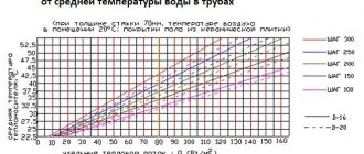
Limit for adjusting the temperature of a heated floor with a three-way valve
The temperature adjustment range is extensive. The upper limit is limited by the capabilities of the boiler - by completely shutting off the cold flow, we get a direct supply of hot coolant into the system. Otherwise, by reducing the supply of hot water, we will achieve cooling. The heating in this case is practically unnoticeable.
Helpful information! It does not matter whether a three-way valve is used for a solid fuel boiler or whether electricity is used for heating. This does not change the structure and technical characteristics of the shut-off valves.
Properly selected and installed shut-off valves will ensure a comfortable temperature in the home
Areas of application
The three-way valve, the operating principle of which was discussed above, has a fairly wide range of applications. Thus, its varieties, such as an electromagnetic device or a device with a thermal head, are often found in modern pipelines, where it is necessary to adjust the proportions when mixing two separated liquid streams, but without reducing power or volume.
As for household use, the most popular here is considered to be a thermostatic mixing device, with which, as noted above, you can regulate the temperature of the working fluid. This liquid can be supplied both to the “warm floor” pipeline and to heating radiators. And if the valve also has automatic control, then you can control the temperature in your home without any problems!
Note! The use of a three-way valve in a heating system to balance temperature changes is extremely beneficial not only in terms of comfort and convenience, but also in terms of cost savings.
The fact is that by regulating the temperature of the liquid at the “return” of the heating device, you can significantly reduce the volume of fuel consumed, and this will have a positive effect on the efficiency of the system itself. In some systems, a valve is simply necessary. For example, in a “warm floor” system, this device prevents overheating of the floor covering above a given comfort level, thereby relieving users of unpleasant sensations.
Regulating devices of this kind are also used in water supply systems in order to obtain a permanent flow at the required temperature. The simplest example is an ordinary mixer, in which you can make water hotter/cooler by opening/closing a cold tap.
Safety valve for boiler
Previously, we described how to select and connect a safety valve for a boiler, talked about its areas of application and internal structure. In addition to this article, we recommend that you read: all the details here
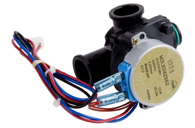
Video instructions for replacing the Secondary DHW Heat Exchanger Navien
All work is carried out with the boiler turned off from the network, with the coolant drained and with the cold water inlet valve on the boiler closed (the pipe on the far right). The reason for replacing the Secondary Heat Exchanger may be poor heating of hot water, a sinusoidal change in temperature (you should also pay attention to the three-way valve), overheating of the main heat exchanger, and low pressure of the DHW system.
If your DHW unit (secondary heat exchanger, three-way valve, temperature and flow sensors) Navien is faulty and you need to repair or replace this unit, we recommend contacting our specialists by phone. All spare parts are available at our warehouse in St. Petersburg
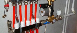
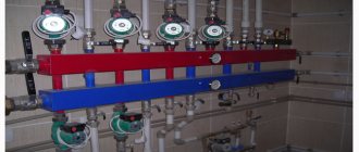
Rooms with many circuits
If a base with a large number of contours is being installed, it is more advisable to divide the premises into certain areas. In these areas, the connection to the boiler can be made either using a three-way thermostatic valve or a special device for floor heating.
An acceptable alternative is to install one common mixing unit. This approach requires the valve to be compatible with the controller and actuator. The second allows you to distinguish between the boundary temperatures of pipes. The working fluid enters the distributor or the common manifold. In this case, temperature control is possible using remote thermal heads.
Related article: How to clear a clogged bathroom sink
Switching on the three-way thermostatic valve
The valve design includes a special thermal head and a separate temperature sensor. These additional elements allow you to regulate the temperature. Thus, a constant temperature in the system is achieved. The pump moves the liquid in the pipes, and the three-way valve mixes a certain amount of hot flow into the comb.
A three-way mixer is installed at the return outlet. It is worth noting that this classic valve activation scheme may include an additional circulation pump. Otherwise, heating of the heated floor will be insufficient. This circuit does not work well without a pump.
Related article: Bidet attachment for toilet
Three-way valve
Three-way mixing valve. Schemes and descriptions. Principle of operation.
We will also look at circuits and valves that are capable of stabilizing a given water temperature, both for heating and for water supply. Let's consider schemes for warm water floors.
A three-way control valve is a device designed to switch or mix two different flows into one common flow. In principle, this is the main job of a three-way valve. What is it for?
How about more specific?
The control element in the valve is usually either a specially designed rod that can move in a vertical direction, or a ball that can rotate around an axis. In this case, the control element does not completely close the valve, but redistributes the flow of liquids, thereby mixing them. Please be aware that there are three-way valves on the market that are not capable of stabilizing the outlet temperature. These are ordinary taps that only change flows and serve as a balancing flow setting. Please check the functionality of this valve before purchasing. It is better to familiarize yourself with the characteristics of such valves using the passport. An example of conventional valves that are not able to stabilize the temperature:
Although such valves are often installed on mixing units for heated floors. Also, electric drives can be installed on such valves to regulate them automatically. More about this:
Drawing diagram of a three-way valve:
To understand how a three-way valve works, let's break it down into two balancing valves: You can find out what a balancing valve is here.
To make it easier, let's call input 1 - point 1 (T1), input 2 - point 2 (T2), output 3 - point 3 (T3) and will denote T1, T2, T3 in the diagram. That is:
And we will call the passages in the form of balancing valves B1 and B2. Consider the graph of a conventional three-way valve without temperature stabilization:
When the three-way valve handle is turned 50%, the inlet valves become equal to each other. And mixing occurs evenly. If you turn the handle to 100%, then the graph shows that at point 1 the valve is pressed 100% and the flow does not flow in this direction. This was a general graph for all 3-way valves without temperature stabilization. And each modification has its own rotation of the handle, so I expressed it as a percentage. This three-way valve is a conventional balancing valve. Since the traversable cross-section between two flows is adjusted. That is, the balance between the two input streams is adjusted.
Three-way valve with maintenance of a given temperature level or with a thermostat function.
Let's now look at a three-way valve with a temperature maintenance function. To understand this, consider this diagram:
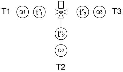
It is very important to understand that each point has its own purpose:
Typically, most three-way valves with stable maintenance of a given point temperature have constant inputs T1, T2, T3. These points are always specific. There are, of course, exceptions, but first you must realize this point that you cannot confuse the dots with each other. In the diagram, these points have a specific meaning. When you learn to understand the principle of operation of three-way valves, you yourself will be able to mechanically check the correctness of the specified points, or read this in the passport. And so let's return to this diagram:
Here t°1, t°2, t°3, in the circle, these are thermometers that show the temperature of the passing liquid. Q1, Q2, Q3 are flow meters that show the amount of passing water volume per unit time. Q3=Q1+Q2 That is, the amount of passing fluid at point 3 is always equal to the sum of passing fluid at point 1 and at point 2. (t3*Q3) = (t1*Q1) + (t2*Q2) Therefore: t3 = ((t1 *Q1) + (t2*Q2))/Q3 Graph of three-way control valve with thermostat function:
The graph is built under the condition: The set temperature is set to 40 degrees. Below is a graph for the flow area of the input points:
Provided that at point 2 the temperature is constant and equal to 20 degrees. The graph shows that the temperature of the incoming flow at point 1 closes the cross section so as to stabilize the outlet temperature at point 3. When the temperature reaches 40 degrees at point 1, the flow section of point 1 begins to close, thereby reducing the flow of hot water at point 1. But, at the same time, it’s time that point 2 begins to open, which lets in a cold stream. Further, already at 60 degrees, intensive mixing of the two flows occurs by 50%. Thus, by diluting hot water with cold water at the outlet at point 3, we obtain a stabilized temperature.
How does a three way valve work?
That is, in a three-way valve with a thermostat there is a mechanism that, sensing the output temperature, strives to make a balancing adjustment of the input flows in order to stabilize the output temperature. By opening the flow more either for point 1 or for point 2. For water supply, this makes it possible to constantly have one set water temperature for hot water supply. While the water heater contains water with a constantly changing temperature. For heating systems, this makes it possible to have a constantly set circulation temperature in some circuits. For example, to supply heated floors with a given temperature, or for example, to stabilize the output temperature from the boiler or to the boiler. Here, for example, is a three-way ESBE valve with a thermostat function:
Important point! Most valves with a thermostat function have one unpleasant feature: the flow area of the inlet points. They are usually very narrowed. This indicates their significant local hydraulic resistance. Even if they have 1 thread. Or the internal passage of the tube is 25mm. Their thread flow area is 4 times smaller, or even larger. For point 2 in general, the flow area is even smaller. Well, this is for valves intended for water supply. For water supply, as a rule, a large flow rate at point 2 is not needed. Therefore, at point 2 the flow area is much lower. But even such a valve can be installed on a mixing unit for heated floors. But, according to a special connection diagram, which will be discussed below. In general, this valve with a thermostat is a universal device. It can be used for both water supply and heating. You just need to choose the right parameters and connect correctly. More on this below. Even if store consultants tell you that this valve is only needed for water supply. I assure you, I know how to make this device also serve for heating. You need to follow some rules, which will be described below. And I almost forgot! There are also alternatives to three-way valves on the market - the three-way thermostatic valve. They call them the same thing, but they carry a thermostatic valve. That is, if you look at the diagram, it looks like this:
The kit should include a thermal head with a remote sensor. Point 2 and point 3 are constantly open. Only point 1 is adjustable. This three-way valve is only suitable for the mixing unit of heated floors. If you decide to take one for yourself, then make sure there are no narrowings at point 2. Whether the flow passing from point 2 to point 3 is able to pass without significant hydraulic resistance. Check for a passable section and see if there are any narrowings. If there are narrowings, then take this into account. And you shouldn’t rely on a good pass at these points. You can make an alternative circulation ring for the mixing unit, which I will discuss below. The connection diagram for a three-way valve is different, but the operating principle is the same for all.
We collect schemes for water supply.
The most common scheme for connecting a three-way valve to stabilize water temperature is:
Here, check valves serve to prevent the flow from producing reverse flows. That is, so that the dynamic pressure difference between cold and hot water does not result in the flow of hot water into cold water and vice versa. Usually this is a rare occurrence and may not happen, but sometimes such incidents happen. You can learn how a check valve works here. Here is a photo where such a circuit is mounted:
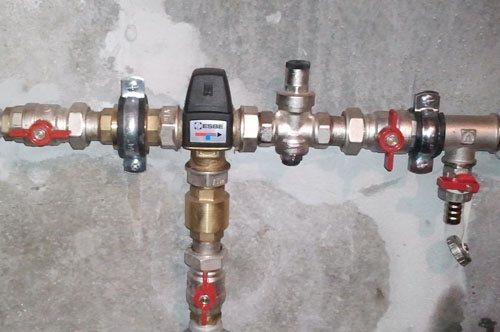
The control knob is hidden under a black cover that is removable. Today, for water supply, there is still one common scheme for stabilizing the temperature.
We assemble circuits using a three-way valve for heating.
For heating, there are currently only three areas where such a valve is needed:
Let's look at the diagram. Three-way valve for underfloor heating:
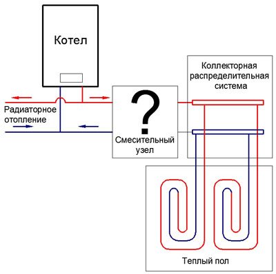
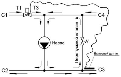
Let's designate the mixing block itself:
The main task of the mixing unit is to create an additional circuit with a separate circulation ring. Therefore, each mixing block has 4 points. The two on the left (C1, C2) are circulation to obtain heat as needed. And the two on the right (C3, C4) are a direct connection to the distribution manifold for powering individual underfloor heating circuits. Thus, at the outlet (C3, C4) there is a constant circulation of coolant. And at the inlet (C1, C2) flow occurs as needed to maintain the temperature at a given level.
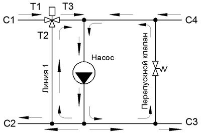
Diagram of a mixing unit with a three-way valve with thermostat function:
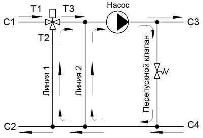
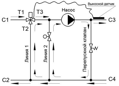
Arrows indicate flow directions. You will have two questions! Why is line 2 and why is a bypass valve ? You can read about the bypass valve here. Line 2 is needed in order to increase the pump flow. This is done because most three-way valves have a narrowing at point 2, which creates hydraulic resistance. Thus, whatever one may say, the pump flow rate will be small if you do not install line 2. And if the pump flow rate is small, then you will not get an economic system. The pump will work at a higher load, which leads to additional energy consumption. Also, you will not be able to pump a large number of circuits (for example, 6-8 circuits). If you find a three-way valve that has a good passage at point 2, then you don’t have to install line 2. Don’t worry about line 1. There will always be flow on line 1, even if you put a pipe with the maximum diameter on line 2. For example, 32mm. It is imperative that the passage of line 2 must be made of the original diameter, the same as the approaches to the pump. When the flow or flow rate on line 1 decreases to critical, a situation may arise when the heat flow into the mixing unit is not sufficient. And the underfloor heating circuits may not be heated enough. If this happens and the floors cannot heat up, then this is due to the fact that there is little circulation between points C1 and C2. And accordingly, there is not enough heat coming. For what reasons does this happen:
If you suspect that there is not enough flow on line 1, then you can either narrow line 2 or install a balancing valve on line 2. With a balancing valve, you can adjust the flow through the valve more accurately.
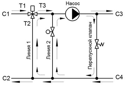
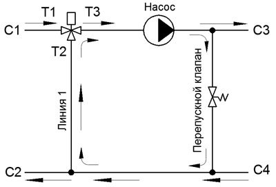
Typically, the circulation flow rate (C1, C2) is always less than the circulation flow rate (C3, C4). By pressing the balancing valve, you increase the flow through line 1, thereby increasing the circulation flow (C1, C2). You also increase the load on the pump. The main thing is to achieve a good balance between a favorable load on the pump and circulation between (C1, C2). There is also such a scheme:
This circuit allows you to get rid of the balancing valve. Only the pump is already in place of line 2. Keep in mind that with this scheme, the output flow from the mixing unit will be equal to the temperature at the inlet to the heated floors. That is, points C2 and C3 will be the same in temperature. Please note that C3 and C4 are swapped. That is, in this diagram, point C3 is at the bottom and point C4 is at the top. You can, of course, save on materials and make a warm floor with a regular three-way balancing valve, as in the diagram:
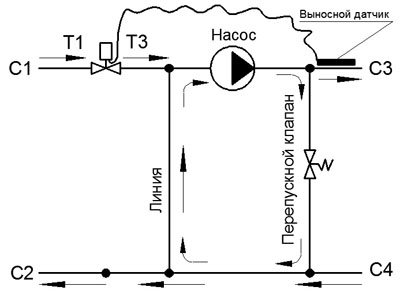
In addition, conventional three-way balancing valves have a good passage, which makes it possible not to use additional line 2. But you must agree that maintaining a set temperature is much more reliable for a heated floor system. Let's look at a diagram of how to connect another three-way valve with a thermostatic valve that has a thermal head with a remote sensor.
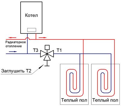
The remote sensor is applied to the supply pipeline of point C3. In this diagram, the input of point 2 can be muted, since it does not play a role at all with a remote sensor. This circuit can be replaced with a two-way thermostatic valve:
There are, of course, all sorts of modifications of the circuits, but we will not consider them, since the other circuits that I saw did not impress me with the special functionality and usefulness of their action. Well, okay, I’ll show you a couple of schemes that I don’t particularly like:
How can I use a three-way valve with a thermostat for one circuit?
For example, let's take a situation: You have one small place in a private house where you want to make a warm water floor. For example, this is the bathroom. In order not to block a super-heavy mixing unit, you can make a heated floor from just one circuit. Here's the diagram:
There are some conditions! The length of the pipe should not exceed 30-40 meters. It all depends on how busy your system is with circuits. If you exceed the length of the pipe, you will get too much hydraulic resistance and the liquid in the pipe will simply flow very weakly. A three-way valve with a thermostat must be placed on the cooled return pipeline. In the direction as indicated in the diagram. The flow goes from point 1 to point 3. Point 2 is jammed and remains free. Thus, automatic regulation of the temperature of the heated floor is obtained. A cooled thermostat tries to open the flow, thereby increasing the flow, and when a hot flow arrives, this means that the pipe is heated and the flow is closed, thereby reducing the flow. But, if you have a large floor area, then you can make two identical contours in parallel with a length not exceeding 30-40 meters. It is very important to make two circuits of equal length so that they have the same hydraulic resistance. Then the liquid will flow evenly along both circuits:
Three-way valve for boiler.
And finally, I’ll show you how to connect the boiler so that no cold flow enters the incoming boiler pipeline. Why is this necessary? Just ask me! And I will answer! In order to prevent condensation from forming on the incoming pipeline and there are no large temperature differences that can lead to deformation of the pipeline at the joints. Here's the diagram:
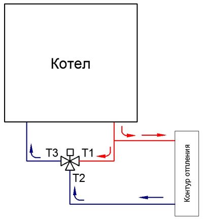
Typically, solid fuel boilers are connected using this scheme, where the temperature can range from 50 to 90 degrees. According to this scheme, the condition is met that the boiler inlet cannot reach a temperature below 50 degrees. This gives a small temperature difference, at which less condensation and temperature overload occurs. Condensation is not desirable as it destroys iron pipes. That is, pipes can become overgrown with rust and quickly become unusable. Pipes quickly rust when exposed to condensation. Typically, such a scheme is installed on high-power solid fuel boilers from 30 kW. And there are also three-way valves on the market for high flow rates. For example, there is a three-way valve with an electric drive. Typically, such valves have good flow and good flow. Read more: Three-way valve with electric drive ESBE Also, if you have a solid fuel boiler and there are plastic pipes, then in such schemes it is recommended to install a three-way valve in order to eliminate high temperatures from entering the plastic pipes in order to save the pipes from destruction. For plastic pipes, temperatures of 85 degrees and above have a detrimental effect. Therefore, it is not recommended to exceed 85 degrees. It’s better to set the thermostat to 75 degrees. Here is a diagram that prevents the passage of high temperature from the boiler into the system with plastic pipes:
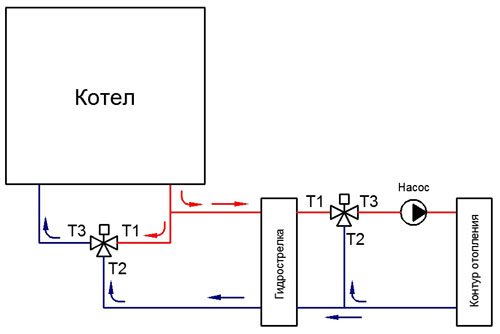
The hydraulic arrow will be described in other articles, but I will only say that the hydraulic arrow is necessary to separate flows with the possibility of heat transfer. That is, the hydrastrel forms two circulation rings near itself, which mix with each other. Valves with a thermostat function are not suitable for this scheme, since they have a very small cross-sectional opening. Keep in mind! Maybe you will find valves with good flow. But I’m warning you just in case. Please pay attention to the good passage in these valves so that the flow in the heating system is sufficient. And so, of course, you can find valves with high flow rates. But be sure to ask and study the characteristics of the valves according to the flow charts when purchasing. So that the same narrowings do not arise that will reduce the consumption of the heating system. You can read about how to make warm water floors here. We'll leave it at that. I hope this article helped you understand the operating principle of these valves. And then you can select the valves yourself for your specific purpose. The connection diagram for a three-way valve is already known to you. The selection of a three-way valve according to its characteristics already falls on your shoulders. I hope that someone will be able to install the three-way valve themselves. Since installing a three-way valve is not fraught with miracle secrets. It is enough to wind it on flax or fum tape and screw it to the pipeline as indicated in the diagrams. The main thing is to understand the physics of fluid flows, and the rest will come from experience!
Types of three-way valves and their features
There is a generally accepted classification of three-way valves, according to which they are divided into separating and mixing. Externally, both types of devices are identical, but inside they have significant differences:
- Mixing devices have one spherical valve inside, located in the center of the chamber. It blocks the flow of the working medium from the supply passage.
- Dividing valves have two valves inside connected to a stem. When adjusting the position of the rod, one of the valves is pressed against the seat and blocks the flow of the working medium into one circuit, opening in parallel the flow of hot water into the other circuit.
We recommend that you read: How a water valve works and the features of its repair
According to the control method, three-way valves are divided into devices with manual and mechanical drive:
- Manual valves have a fairly simple design, reminiscent of a conventional ball valve. A manual shut-off device can be installed where there is no need to strictly regulate the temperature of the working environment, for example, when distributing coolant between heating radiators of different capacities.
- The electrically driven device operates with the participation of a thermostat equipped with a sensitive temperature sensor, which provides it with almost complete autonomy. For its operation, it is enough to set the temperature range, and the valve itself will dose cooled and hot water to maintain the desired hydraulic regime.
Note! Automatic valves with an electric drive are usually installed in systems where a “warm floor” is connected to the boiler along with a conventional heating system.