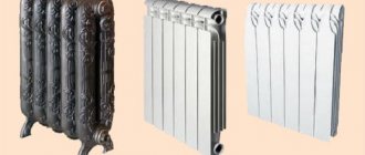
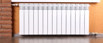
Aluminum radiators, what could be better? The weight is 2.5-3 times less than that of iron or cast iron, and the thermal conductivity is 3 times greater than that of iron and almost 5 times greater than that of cast iron.
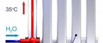
What weight gives is clear to everyone, it is less load on the fastenings, on the wall, less weight during transportation and lifting to the floor. Thermal conductivity is the ability of a material to conduct heat through itself; the higher it is, the faster the metal of the radiator releases the energy of the coolant and the faster it cools when heating is not needed.
Aluminum is an ideal material for radiators. Lightweight and beautiful. The only cooler thing is copper, which has the same thermal conductivity as aluminum, but is heavier than iron and more expensive.
But is aluminum really perfect? Let's consider its properties and various nuances.
Aluminum, when reacting with air (oxygen), forms on its plane a thin film of aluminum oxide, which does not react further with water and acids, but is quite easily dissolved by alkalis.
4Al+3O2 = 2Al2O3 Or with water, forming the same oxide film and free hydrogen. 2Al+3H2O = Al2O3 +3H2
Everyone knows this problem with hydrogen emissions on aluminum radiators. But it doesn’t last that long, it will all end when this protective oxide film forms on the surface of the aluminum. When you read in the description of aluminum radiators that there is a protective coating on the inner surface, it means that most likely the manufacturer has already allowed the surface to become coated with oxide by placing the radiator sections in water or in humid air. If there is no oxide film yet, it will appear upon contact with the coolant (if it is water), and for some time the released hydrogen will be removed by automatic air vents, reducing the pressure in the system, while some panic, thinking that they have a leak.
Sometimes, with different nuances, the oxide film can be damaged by debris, sand in the heating system, after which a new reaction of aluminum with water occurs and an oxide film grows. This is a very short process, because damage to the film is usually minimal.
This is where all the user’s misadventures with aluminum radiators end if he has an autonomous system and water as a coolant. If there is some kind of “anti-freeze”, then there may be nuances. Standard anti-freeze agents based on propylene glycol (which are recommended for heating systems due to their less aggressiveness than ethylene glycol) do not react in any way with aluminum. But homemade “bad” mixtures can damage the integrity of the oxide film on aluminum.
If it suddenly happened that the user risked installing an aluminum radiator for central heating, then this is tantamount to a time bomb. What happens then?
It is no secret that in central heating systems, alkali is added to the coolant to wash all its parts (especially metal ones) and prevent corrosion. At the same time, an alkaline pH is constantly maintained.
In this case, a reaction occurs between the protective film of aluminum oxide and dissolved alkali in the coolant.
Al2O3 + 2NaOH + 7H2O = 2Na[Al(OH)4(H2O)2] which later decomposes into 2NaAlO2 + 8H2O, that is, into sodium aluminate and water. But this compound is not stable and reacts with water again, becoming sodium tetrahydroxoaluminate Na[Al(OH)4]. But this complex salt is also unstable and breaks down into other complex salts, but this is not the main thing, the main thing is that the aluminum oxide film ceases to protect the aluminum of the base. and it begins to react with the alkali coolant
2Al+2NaOH+6H2O = 2Na[Al(OH)4]+3H2 Again with the evolution of hydrogen and the formation of sodium tetrahydroxoaluminate. So the alkali of the coolant eats up the body of the radiator. The reaction products are carried away by the coolant and a new portion of the alkaline coolant is delivered. Aluminum is simply washed away with alkali.
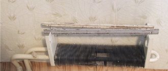
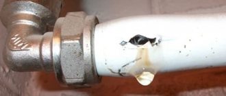
Over time, in some thin places, the radiator may burst due to the fact that the aluminum layer cannot withstand the pressure in the heating system (or due to water hammer).
But here there are also the nuances of manufacturing aluminum radiators. Let's consider them too.
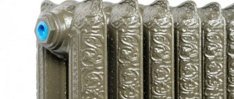
If radiators are made by casting, where aluminum is melted and then poured into molds and it creates a crystalline structure, then its structure is something like this
Description of the block from Aliexpress
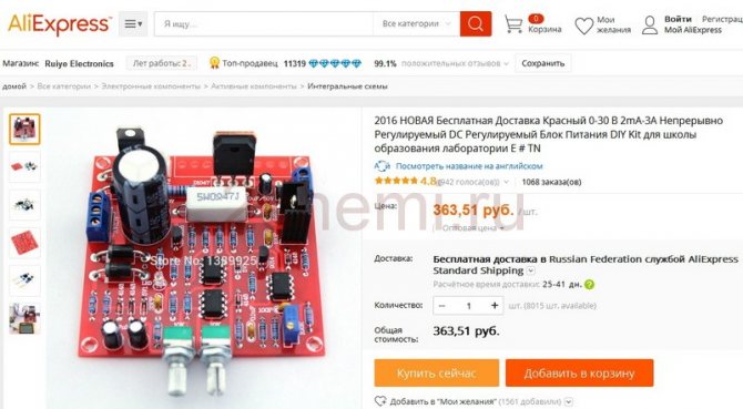
AliExpress kit for assembling a power supply
Yes, if only then, as now, it was possible to place an order in the AliExpress online store for a kit of electronic components for assembling a power supply (here is its diagram). Only 360 rubles compared to the offer in the store of a simple ready-made power supply for 1800 rubles, albeit already encased, but with more modest output characteristics. If there is 0 - 30 V and a current of up to 3 A, then there is 0 - 15 V and a current of up to 2 A (power supply ELEMENT 1502DD).
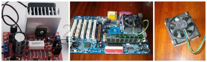
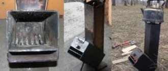
PC cooler for PSU
Power supplies are not soldering irons, and they don’t often fall into disrepair, but it happens, there is such a precedent in the asset, so I decided to order it, let it be. I read the reviews on the Internet - they are not bad, one might even say good, but with a reservation. The power supply gets pretty hot and using it without a radiator with forced cooling is unrealistic. IMHO, well, what a load to put on it. I took a closer look and in the bottom photo of the order I actually saw the cooler installed on the board. Well, we can solve this issue easily, you can always find such a historical motherboard, no longer needed by anyone, for a nominal fee and remove what is needed from it.
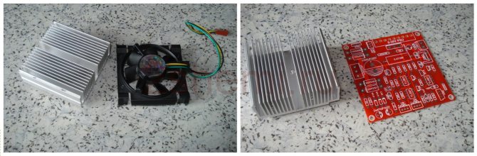
Radiator and fan for transistor
And so I place an order for a DIY Kit and receive it in 20 days. I was surprised by the accuracy of the values of electronic components, everything is within a tolerance of 1%. Now we need to integrate the cooler into the power supply board. I disconnect the fan from the radiator and put them in order. The radiator is washed, the fan is lubricated and put aside for now. It was a little disconcerting that the board and heatsink are almost the same size, but everything can be done if desired.
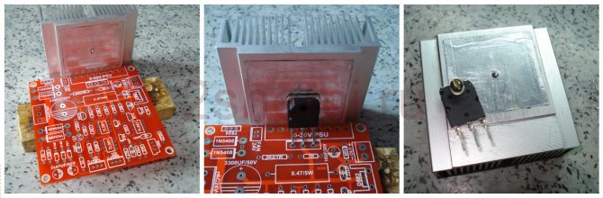
Transistor for power supply radiator
Finally, the optimal mutual position has been found, don’t look at the hole in the center (it’s as if it’s not there yet). First, we take the power transistor, bend its leads accordingly and align them with the soldering point on the board, and install the transistor body strictly in the middle (at horizontal) radiator. In this case, there is no radiator plate in the hole on the back side. We mark, drill a hole with a diameter of 2.6 mm and cut an M3 thread.
Useful: Power supply 0-50 Volt 0-20 Ampere
| Date added: 2008-05-15 | |
10.1. Purpose of radiators
— remove heat from semiconductor devices, which makes it possible to reduce the temperature of pn junctions and thereby reduce its influence on the operating parameters of devices. Plate, finned and pin radiators are used. To improve heat dissipation, it is best to attach a semi-conductor device directly to the radiator. If electrical isolation of the device from the chassis is necessary, the radiator is attached to the chassis through insulating gaskets. The heat-emitting ability of a radiator depends on the degree of blackness of the material (or its surface) from which the radiator is made:
| Oxidized aluminum Silumin Duralumin D16 Oxidized copper Polished copper Dull brass | 0,2-0,3 0,2-0,3 0,37-0,4 0,57 0,03 0,22 | Oxidized steel Polished steel Aluminum paint Bronze paint Enamel paints, varnishes | 0,86-0,92 0,07 0,28 0,51 0,92-0,98 |
The higher the degree of blackness, the more efficient the heat dissipation will be.
10.2.
A pin radiator is a very effective heat sink for semiconductor devices. To make it, you need sheet duralumin with a thickness of 4-6 mm and aluminum wire with a diameter of 3-5 mm. On the surface of the pre-processed radiator plate, the locations of the holes for the pins, transistor (or diode) terminals and mounting screws are marked with a center punch. The distance between the centers of the holes (pitch) for the pins in a row and between the rows should be equal to 2-2.5 times the diameter of the aluminum wire used. The diameter of the holes is chosen so that the wire enters them with the smallest possible gap. On the reverse side, the holes are countersunk to a depth of 1-1.5 mm. A mandrel is made from a steel rod 80-100 mm long and B-10 mm in diameter, for which a hole with a diameter 0.1 mm larger than the diameter of the wire is drilled in the end of the rod. The depth of the hole should be equal to the height of the future radiator pins.
Rice. 10.1. Crimper for radiator pins
Then the required number of pin blanks is cut. To do this, a piece of wire is inserted into the hole in the mandrel and cut off with wire cutters so that the length of the end protruding from the mandrel is 1-1.5 mm greater than the thickness of the plate. The mandrel is clamped in a vice with the hole facing up, a pin blank is inserted into the hole, onto the protruding end of which a plate is placed face down and riveted with light blows of a hammer, trying to fill the countersunk recess. All pins are installed in this way. A pin heatsink can also be made using a slightly different method of installing the pins in the holes in the base plate. A steel crimp is made, the drawing of which for pins with a diameter of 3 and a length of up to 45 mm is shown in Fig. 10.1. The working part of the crimp should be hardened. The pin is inserted into the hole in the base of the radiator, the base is placed on the anvil, a crimp is put on top of the pin and it is hit with a hammer. A ring groove is formed around the pin, and the pin itself is tightly seated in the hole. If it is necessary to make a double-sided radiator, then two such crimps will be required: a pin is inserted into one of them, installed on the anvil with the hole facing up, the base of the radiator is threaded, and the second crimp is put on top. By hitting the upper crimp with a hammer, the pin is fixed on both sides at once. This method can be used to produce radiators from both aluminum and copper alloys. Finally, the pins can be installed using soldering. To do this, use copper or brass wire with a diameter of 2-4 mm as the material. One end of the pin is tinned to a length greater than the thickness of the plate by 1-2 mm. The diameter of the holes in the plate should be such that the tinned pins fit into them without much effort. Liquid flux is injected into the holes in the base (Table 9.2), pins are inserted and each of them is soldered with a powerful soldering iron. At the end of the work, the radiator is washed with acetone.
Rice. 10.2. Heatsink for a powerful transistor
10.3. Sheet copper radiator
1-2mm thick can be made for powerful transistors such as P210, KT903 and others in similar packages. To do this, a circle with a diameter of 60 mm is cut out of copper, and holes are marked in the center of the workpiece for attaching the transistor and its leads. Then, in the radial direction, the circle is cut 20 mm with metal scissors, dividing it into 12 parts around the circumference. After installing the transistor, each sector is turned 90° and bent upward.
10.4. Radiator for powerful transistors
type KT903, KT908 and others in similar cases can be made from aluminum sheet 2 mm thick (Fig. 10.2). The specified dimensions of the radiator provide a radiating surface area sufficient to dissipate power on the transistor up to 16 W.
Rice. 10.3. Radiator for low-power transistor: a-scan; b - general view
10.5. Radiator for low-power transistors
can be made from sheet red copper or brass 0.5 mm thick in accordance with the drawings in Fig. 10.3. After all the cuts have been made, the reamer is rolled into a tube using a mandrel of the appropriate diameter. Then the workpiece is tightly placed on the transistor body and pressed with a spring ring, having previously bent the side mounting ears. The ring is made of steel wire with a diameter of 0.5-1 mm. Instead of a ring, you can use a copper wire bandage. Then the side ears are bent down, the cut “feathers” of the workpiece are bent outward to the desired angle - and the radiator is ready.
10.6. Radiator for transistors of the KT315, KT361 series
can be made from a strip of copper, aluminum or tin 2-3 mm wide than the width of the transistor housing (Fig. 10.4). The transistor is glued into the radiator with epoxy or other glue with good thermal conductivity. For better thermal contact between the transistor housing and the radiator, it is necessary to remove the paint coating from the housing at the points of contact, and install it into the radiator and gluing it with the minimum possible gap. Install the transistor with the radiator on the board, as usual, with the lower edges of the radiator touching the board. If the width of the strip is 7 mm, and the height of the radiator (made of tinned sheet metal 0.35 mm thick) is 22 mm, then with a dissipation power of 500 mW, the temperature of the radiator at the place where the transistor is glued does not exceed 55 ° C.
10.7. Radiator made of “fragile” metal,
for example, from sheet duralumin, made in the form of a set of plates (Fig. 10.5). When making gaskets and radiator plates, it is necessary to ensure that there are no burrs on the edges of the holes and on the edges of the plates. The contacting surfaces of the gaskets and plates are carefully sanded with fine-grained sandpaper, placing it on a flat glass. If it is not necessary to isolate the transistor housing from the device body, then the radiator can be mounted on the wall of the device body or on the internal partition without insulating gaskets, which ensures more efficient heat transfer.
10.8. Mounting diodes type D226 on a radiator
or on a heat sink plate. The diodes are secured using a flange. The cathode terminal is bitten off at the very base and the bottom is thoroughly cleaned with fine-grained sandpaper until a clean, flat surface is obtained. If it is necessary to leave the cathode terminal, then drill a hole in the radiator for the terminal, remove the varnish from the bottom with acetone and carefully file off the side (rim) of the diode flush with the bottom for better thermal contact of the diode with the radiator.
10.9. Improved thermal contact
between the transistor and the heatsink will provide greater power dissipation on the transistor. Sometimes, especially when using cast radiators, removing cavities and other surface imperfections at the point of thermal contact (to improve it) can be difficult, and sometimes impossible. In this case, a lead gasket will help. The lead plate is carefully rolled or flattened between two smooth flat bars to a thickness of approximately 10.5 mm and the spacer is cut out to the required size and shape. Both sides are cleaned with fine-grained sandpaper, installed under the transistor and the assembly is tightly compressed with screws. The gasket should not be thicker than 1 mm, since the thermal conductivity of lead is low.
10.10. Blackening of aluminum radiators.
To increase the heat transfer efficiency of the radiator, its surface is usually made matte and dark. An accessible method of blackening is treating the radiator in an aqueous solution of ferric chloride. To prepare the solution, an equal volume of ferric chloride powder and water is required. The radiator is cleaned of dust and dirt, thoroughly degreased with gasoline or acetone and immersed in the solution. Keep in the solution for 5-10 minutes. The color of the radiator is dark gray. Processing must be done in a well-ventilated area or outdoors.
DID YOU KNOW?
10.11.
The thermal regime of low-power transistors can be alleviated by placing a torus (“steering wheel”) on the metal body of the transistor - a spiral twisted from copper, brass or bronze wire with a diameter of 0.5-1.0 mm.
10.12.
A good radiator can be the metal case of the device or its internal partitions.
10.13.
The evenness of the radiator contact pad is checked by smearing the base of the transistor with some paint and applying it to the surface of the contact pad.
Protruding areas of contact. The radiator pads will be colored. 10.14.
To ensure good thermal contact, the surface of the transistor adjacent to the heatsink can be lubricated with a non-drying lubricant, such as silicone.
This will reduce the thermal resistance of the contact by one and a half to two times. 10.15.
To improve cooling conditions, the radiator must be positioned so as not to interfere with convection air flows: the fins of the radiator are vertical, and the side on which the transistor is located should be on the side, and not below or above.
Added by: Pavel (Admin) Author:
You may be interested in:
- How to solder SMD. Part two.
- PCB Etching Machine
- How to make a really good board at home
- Technology Tips
- Quartz Frequency Boost